

Driving force control apparatus and method for vehicle
- Summary
- Abstract
- Description
- Claims
- Application Information
AI Technical Summary
Benefits of technology
Problems solved by technology
Method used
Image

Examples
first embodiment
[0036] With reference to the drawings, embodiments of the present invention are hereinafter described. In the following description, like components are denoted by like reference characters. The like components are named similarly and function similarly. Therefore, a detailed description thereof is not repeated.
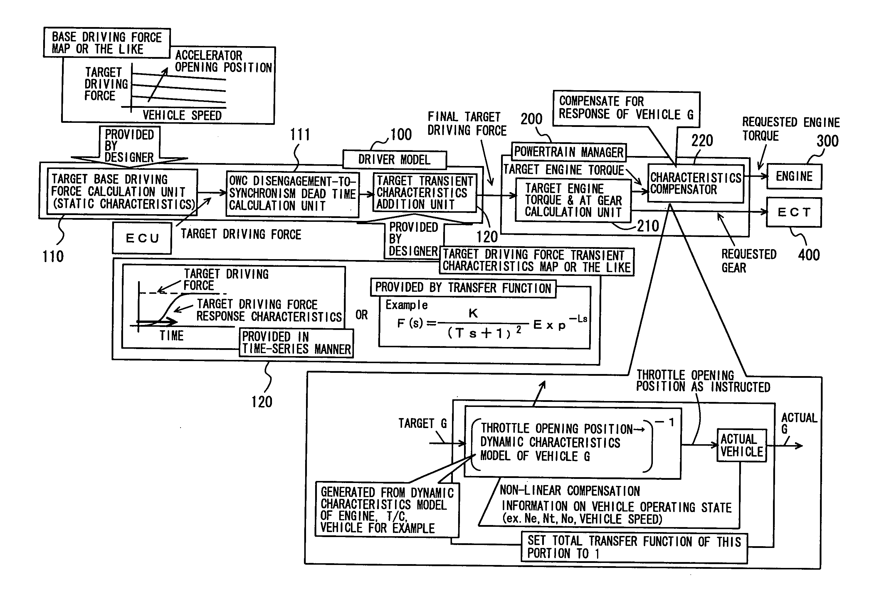
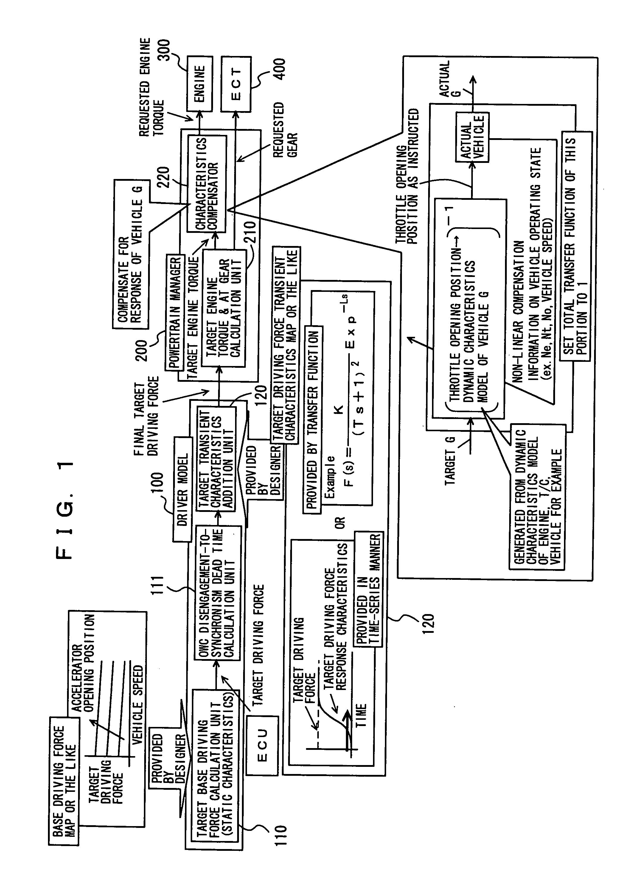
[0037]FIG. 1 shows a control block diagram of a driving force control apparatus according to the present embodiment. This driving force control apparatus is implemented by a program executed by a CPU (Central Processing Unit) included in an ECU (Electronic Control Unit) mounted on a vehicle.
[0038] As shown in FIG. 1, the driving force control apparatus finally outputs a requested engine torque to an engine 300 and outputs a requested gear to an ECT (Electronically Controlled automatic Transmission) 400. It is noted that ECT 400 may be a belt-type CVT (Continuously Variable Transmission). In this case, the output is not the requested gear but a requested gear ratio.
[0039] W...
second embodiment
[0068] A second embodiment of the present invention is hereinafter described. It is noted that similar functions to those of the first embodiment are denoted by similar reference characters. Therefore, the detailed description thereof is not repeated.
[0069] A driving force control apparatus according to the present embodiment does not have OWC disengagement-to-synchronism dead time calculation unit 111 but has an OWC synchronous time powertrain manager 201 and a driver-request-first processing unit 203 in parallel with powertrain manager 200. It is noted that OWC synchronous time powertrain manager 201 is a functional block that is used when the one-way clutch is in the non-driven state (disengaged state).
[0070] As shown in FIG. 3, a final target driving force that is output from driver model 100 is output to any of powertrain manager 200, OWC synchronous time powertrain manager 201 and driver-request-first processing unit 203.
[0071] OWC synchronous time powertrain manager 201 ou...
third embodiment
[0089] A third embodiment of the present invention is hereinafter described. It is noted that, in the following description, similar functions to those of the first embodiment or the second embodiment are denoted by like reference characters including the step numbers. Therefore, the detailed description thereof is not repeated.
[0090] A driving force control apparatus of the present embodiment has a part that executes a program different from that of the driving force control apparatus of the second embodiment.
[0091] Referring to FIG. 5, a control structure of the program executed by the driving force control apparatus of the present embodiment is described. It is noted that, in the flowchart shown in FIG. 5, the same process steps as those of the above-described flowchart in FIG. 4 are denoted by the same step numbers. In the same process steps, the same operation is performed. Therefore, the detailed description thereof is not repeated.
[0092] In S230, the driving force control ...
PUM
 Abstract
Description
Claims
Application Information