Exhaust gas guide of a gas turbine and method for mixing the exhaust gas of the gas turbine

a gas turbine and exhaust gas technology, applied in the direction of machines/engines, combustion types, lighting and heating apparatus, etc., can solve the problems of high pressure loss, limited application, and inability to meet the requirements of continuous application, and achieve the effect of reducing the mixing distance, and reducing the cost of operation

Active Publication Date: 2007-03-01
HOWDEN ROTHEMUHLE GMBH
View PDF5 Cites 86 Cited by
  • Summary
  • Abstract
  • Description
  • Claims
  • Application Information

AI Technical Summary

Benefits of technology

[0012] A further advantage of the present invention is that the largely uniformly turbulent flow behavior of the exhaust gas after the swirl device, which is caused by the leading edge swirls, is less strongly dependent on the gas quantity currently flowing through the flow channel than with the installed surfaces used up to this point. The swirl device therefore does not have to be continuously adapted to every variation of the gas quantity, when the output of the gas turbine is ramped up or down, for example.
[0013] Furthermore, situating burners in exhaust gas guides for auxiliary firing of the exhaust gas flow is known. The burners are frequently operated by fossil fuels, such as natural gas. This natural gas is combusted with the oxygen still contained in the exhaust gas in auxiliary firing. Through this auxiliary firing executed by the burners, the efficiency of a CCGT power plant may be elevated and the flow characteristic of the steam turbine may be tailored to the particular demand.
[0014] Burners of this type generate hot exhaust gas streams in the exhaust gas guide, which must be mixed with the remaining turbine exhaust gas before it flows into the waste heat boiler or the gas diverter. The known exhaust gas guides having burners in the flow channel have the disadvantage that the distance between burner and entry into the waste heat boiler or the gas diverter must be relatively large so the exhaust gas is completely mixed before leaving the exhaust gas guide.
[0015] In a preferred embodiment of the present invention, the swirl device is implemented and oriented in such a way that the leading edge swirls generated thereby mix the hot exhaust gas streams of the at leas

Problems solved by technology

However, constant application of the flow to the expanding flow wall, in particular with increasing opening angle of the flow channel, is only achieved in a limited way us

Method used


Image

  • Exhaust gas guide of a gas turbine and method for mixing the exhaust gas of the gas turbine
  • Exhaust gas guide of a gas turbine and method for mixing the exhaust gas of the gas turbine
  • Exhaust gas guide of a gas turbine and method for mixing the exhaust gas of the gas turbine

Examples


Embodiment Construction

[0048] In the embodiments described in the following, identical components are provided with identical reference numerals.

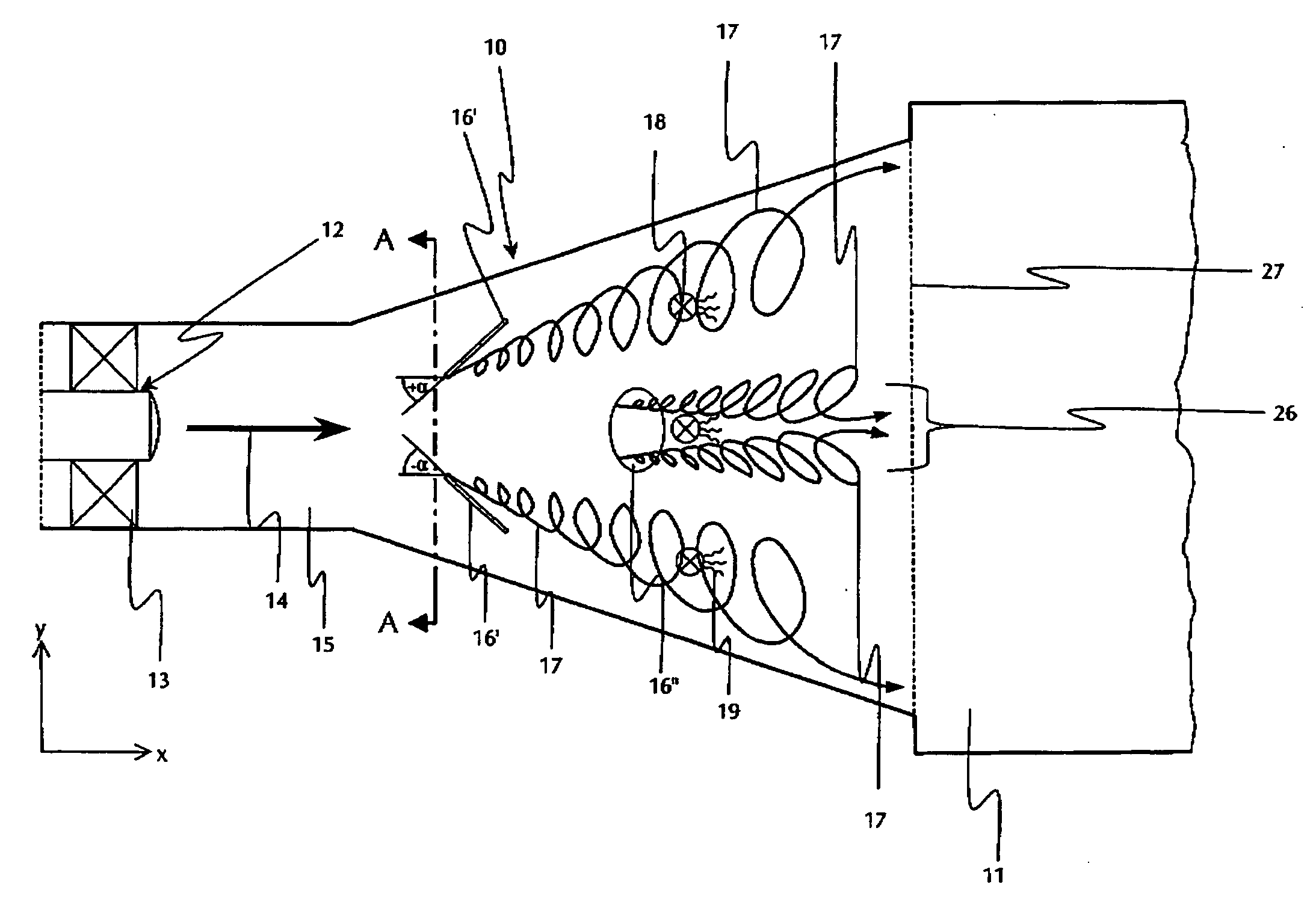
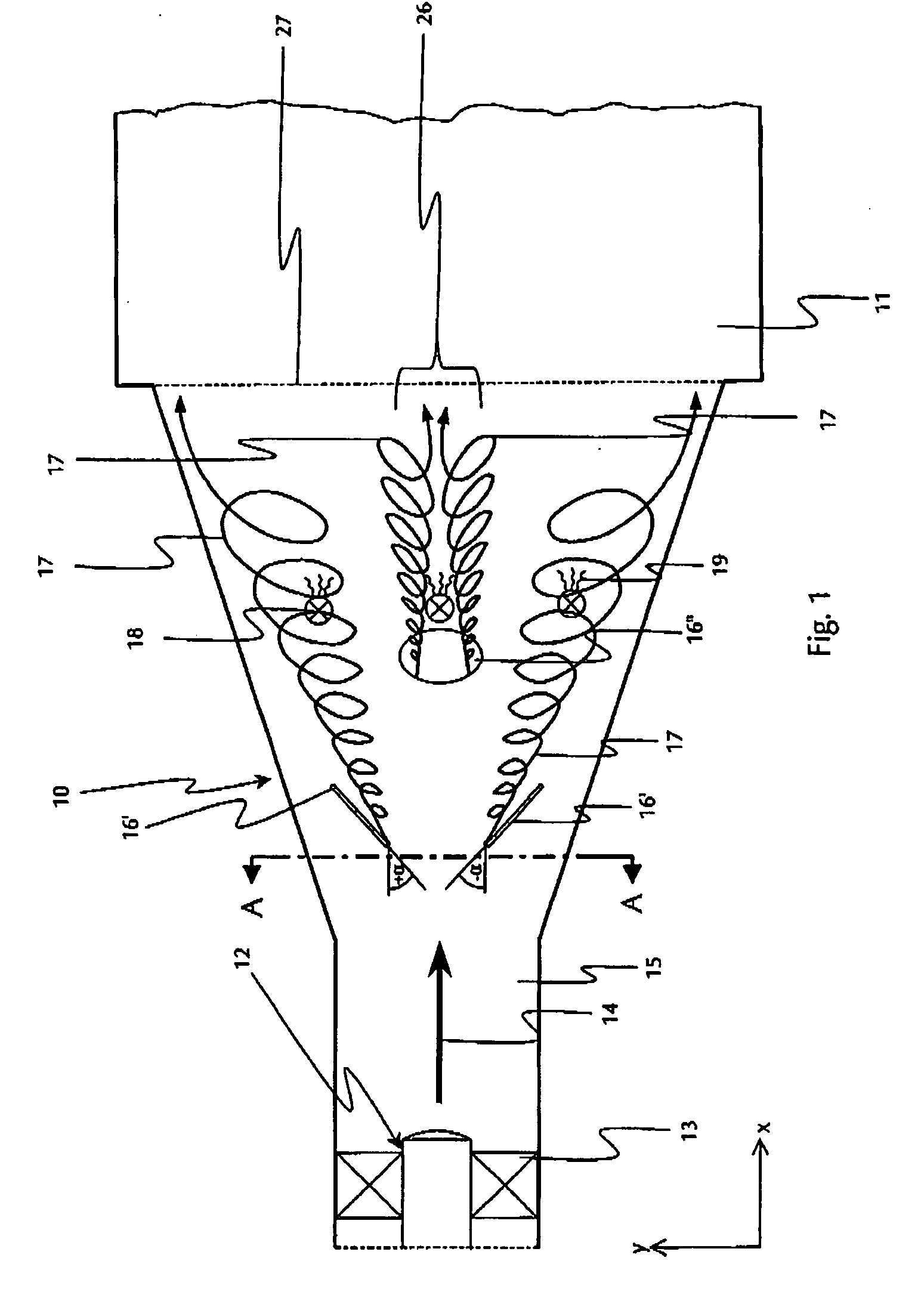
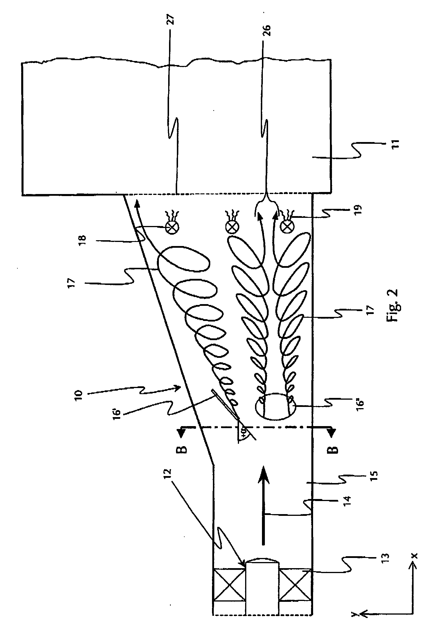
[0049]FIG. 1 shows an exhaust gas guide 10, which has a flow channel 15, which adjoins a gas turbine 12, which comprises blade wheels 13, and discharges into a waste heat boiler 11. The arrow identified by reference numeral 14 identifies the main flow direction of the exhaust gas of the turbine 12. In the exhaust gas guide 10 shown here, the main flow direction 14 runs in the direction of the flow channel longitudinal axis in the x direction. The flow channel 15 is implemented as rectangular and has walls running parallel in its forward area, which directly adjoins the gas turbine 12. In the further course of the flow channel 15, its cross-section expands both downward and also upward, the expansion having a constant slope both in the upper and also in the lower area and continuing up to the connection of the flow channel 15 to the waste heat boiler 11. In the u...


PUM


Abstract

The present invention relates to an exhaust gas guide of a gas turbine, which is situated between the gas turbine and a downstream waste heat boiler or a downstream gas diverter and which comprises a flow channel which has a cross-section expanding in at least some areas in the main flow direction, having installed surfaces influencing the flow. In order to achieve a more compact implementation of the exhaust gas guide and simultaneously avoid or reduce pressure losses, the installed surfaces are implemented as a swirl device generating a leading edge swirl, which is situated in the diverging area of the flow channel and is implemented to distribute the exhaust gas flow uniformly over the flow cross-sectional area upon entry into the waste heat boiler or the gas diverter. Furthermore, the present invention relates to a method for mixing the exhaust gas of a gas turbine with hot exhaust gas streams generated in an auxiliary firing of at least one burner. This thorough mixing is achieved by generating at least one leading edge swirl system in the flow channel.

Description

CROSS-REFERENCE TO RELATED APPLICATIONS [0001] This application claims priority to European Patent Application No. EP 05018270.8, filed Aug. 23, 2005, the disclosure of which is hereby incorporated by reference in its entirety. FIELD OF THE INVENTION [0002] The present invention relates to an exhaust gas guide of a gas turbine, which is situated between the gas turbine and a downstream waste heat boiler and which comprises a flow channel, which has a cross-section expanding in at least some areas in the main flow direction, having installed surfaces influencing the flow, and an exhaust gas guide of a gas turbine, which is situated between the gas turbine and a downstream gas diverter and which comprises a flow channel, which has a cross-section expanding in at least some areas in the main flow direction, having installed surfaces influencing the flow. Furthermore, the present invention relates to a method for mixing the exhaust gas of a gas turbine inside a flow channel which has a ...

Claims


Application Information

Patent Timeline
IPC IPC(8): F02C6/18
CPCF05B2240/122F22B1/1815Y02E20/16F23R3/18F23R2900/03341F23D2900/21003F23C15/00
Inventor LESER, STEFANKAATZ, MICHAELPODHORSKY, MIROSLAV
Owner HOWDEN ROTHEMUHLE GMBH
Why Eureka
Try Eureka