Common rail fuel injection system designed to avoid error in determining common rail fuel pressure
a common rail and fuel pressure sensor technology, applied in the direction of machines/engines, anti-theft devices, electric control, etc., can solve the problem of unsatisfactory change in the drive voltage applied to the sensor element of the fuel pressure sensor
- Summary
- Abstract
- Description
- Claims
- Application Information
AI Technical Summary
Benefits of technology
Problems solved by technology
Method used
Image
Examples
first embodiment
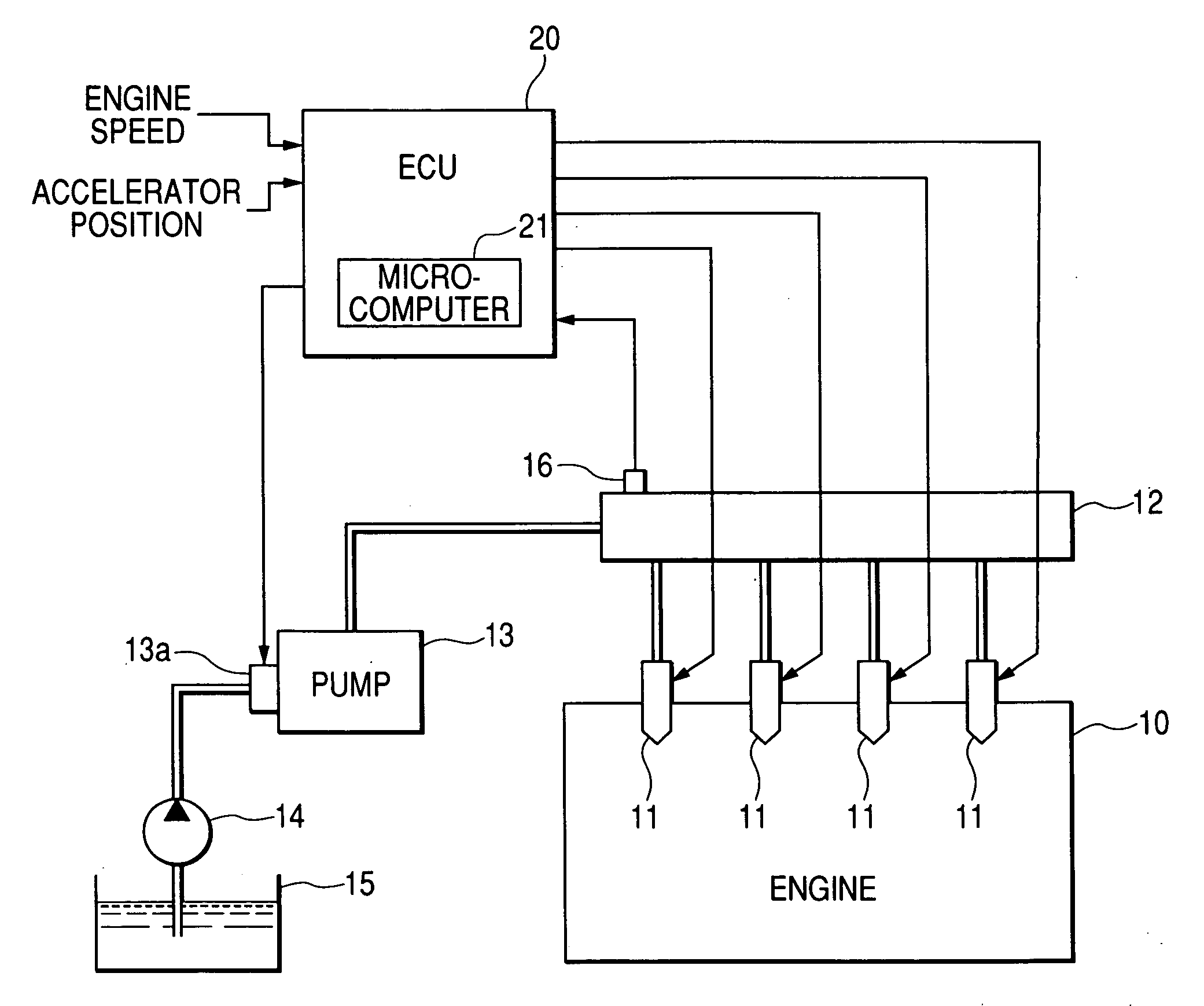
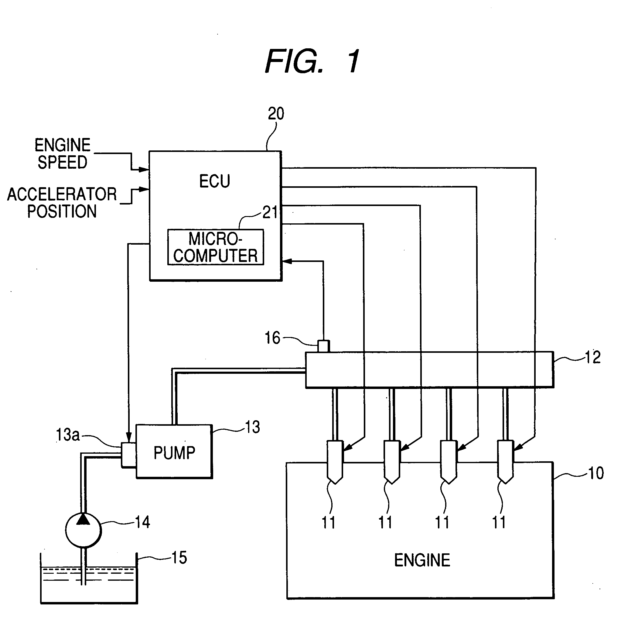
[0031] Referring to the drawings, wherein like reference numbers refer to like parts in several views, particularly to FIG. 1, there is shown a fuel injection system according to the invention which is designed as a common rail fuel injection system (also called an accumulator injection system) working to control injection of fuel into multi-cylinder diesel engines.
[0032] The fuel injection system includes solenoid-operated injectors 11 each for one of cylinders of the engine 10. The injectors 11 are hydraulically connected to a common rail 12 which serves as a fuel accumulator. A high-pressure pump 13 is connected to the common rail 12 and works to supply fuel to the common rail 12 and accumulate it at a pressure substantially equivalent to a required fuel injection pressure. A solenoid-operated suction control valve 13a is installed on the high-pressure pump 13. The high-pressure pump 13 sucks the fuel pumped by a feed pump (i.e., a low-pressure pump) 14 out of a fuel tank 15 thro...
second embodiment
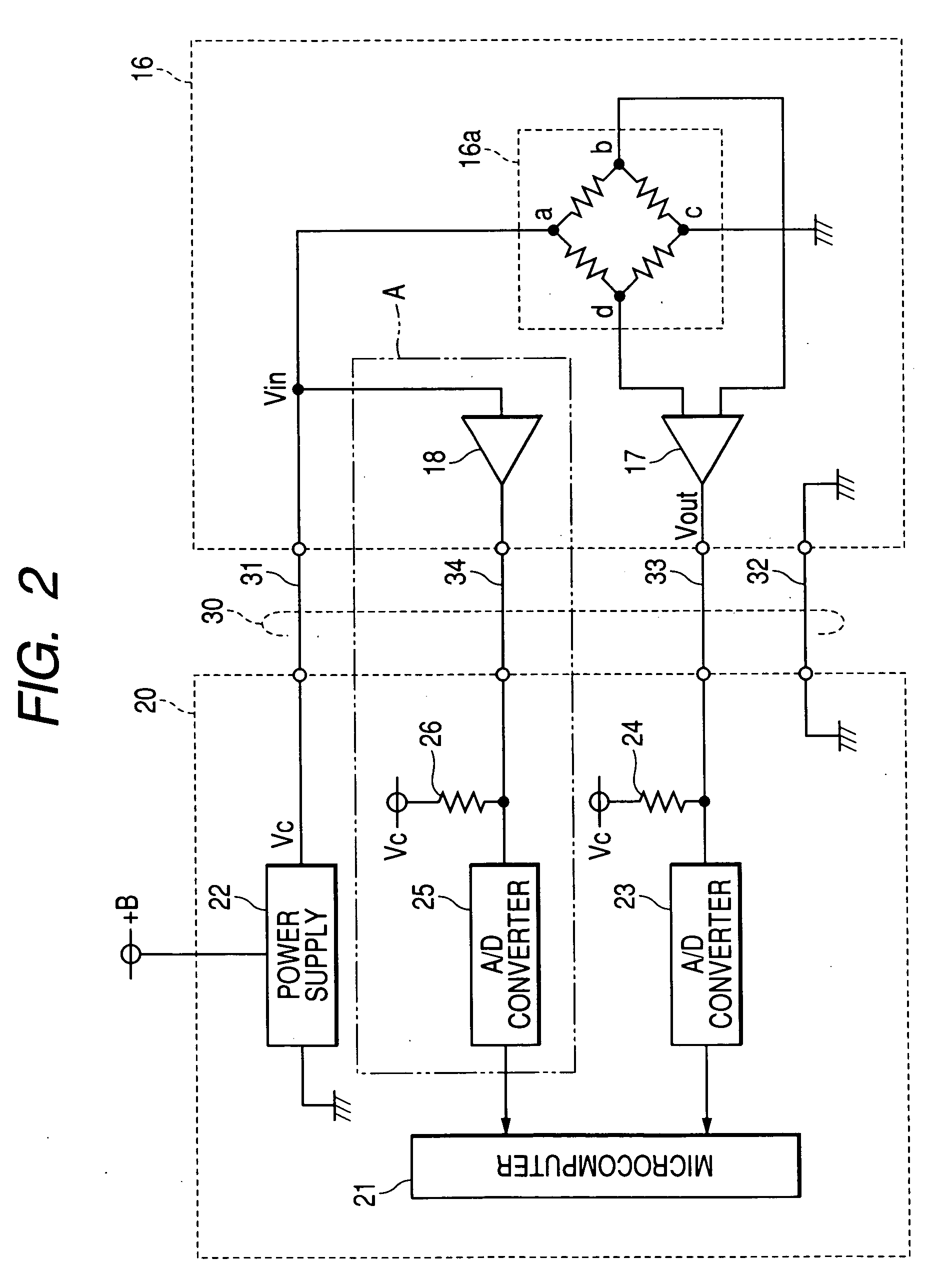
[0058]FIG. 6 illustrates internal structures of the ECU 20 and the fuel pressure sensor 16 according to the invention. The same reference numbers as employed in FIG. 2 refer to the same parts, and explanation thereof in detail will be omitted here.
[0059] The fuel pressure sensor 16 includes an arithmetic circuit 51 made by a microcomputer which works to determine whether the internal drive voltage Vin is in error or not.
[0060] The fuel pressure sensor 16 and the ECU 20 are coupled with each other through a harness 40. The harness 40 consists of three wires and connectors (not shown) joined to ends of the wires. The fuel pressure sensor 16 and the ECU 20 also have connectors mating with the connectors of the harness 40. The ECU 20 includes the power supply circuit 22 which supplies the electric power to the fuel pressure sensor 16 through the power supply line 41. The fuel pressure sensor 16 and the ECU 20 are kept at a common reference potential through the reference potential line...
third embodiment
[0066]FIG. 7 illustrates internal structures of the ECU 20 and the fuel pressure sensor 16 according to the invention. The same reference numbers as employed in FIG. 2 refer to the same parts, and explanation thereof in detail will be omitted here.
[0067] The fuel pressure sensor 16 and the ECU 20 are coupled with each other through a harness 60. The harness 60 consists of three wires and connectors (not shown) joined to ends of the wires. The fuel pressure sensor 16 and the ECU 20 also have connectors mating with the connectors of the harness 40.
[0068] The ECU 20 is equipped with a transistor 71 and a resistor 72. The transistor 71 is connected at a base thereof to the microcomputer 21, at an emitter thereof to the power supply circuit 22, and at a collector thereof to the fuel pressure sensor 16 through the resistor 72 and the power supply line 61. The microcomputer 21, the power supply circuit 22, the transistor 71, and the resistor 72 constitute a power supply unit. The microcom...
PUM
 Abstract
Description
Claims
Application Information
 - R&D
- Intellectual Property
- Life Sciences
- Materials
- Tech Scout
- Unparalleled Data Quality
- Higher Quality Content
- 60% Fewer Hallucinations
Browse by: Latest US Patents, China's latest patents, Technical Efficacy Thesaurus, Application Domain, Technology Topic, Popular Technical Reports.
© 2025 PatSnap. All rights reserved.Legal|Privacy policy|Modern Slavery Act Transparency Statement|Sitemap|About US| Contact US: help@patsnap.com


