
Method of sputter depositing an alloy on a substrate

a technology of sputter and substrate, applied in the field of physical vapor deposition, can solve the problems of different magnetic materials, inability to mix layers, and inability to deposition tools and techniques, and achieve the effect of overcompensating cost disadvantages

Inactive Publication Date: 2007-03-01
VEECO INSTR
View PDF11 Cites 8 Cited by
  • Summary
  • Abstract
  • Description
  • Claims
  • Application Information

AI Technical Summary

Benefits of technology

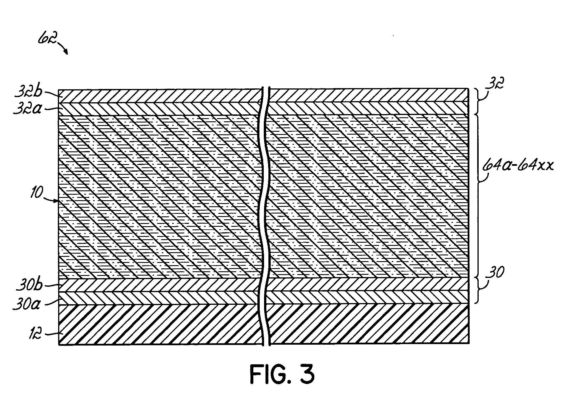
[0011] Accordingly, the thickness of each layer includes a fraction of a mono-atomic layer made possible by planetary sputter deposition allowing for uniform mixing of the layers in the laminate. Each laminate is homogeneous, and each subsequent laminate is continuous with the adjacent laminate to form the alloy. Consequently, conventional stacking of layers is avoided and the sputter deposited amount, or thickness, of each layer of magnetic material(s) may be controlled or adjusted so that different substrates can be provided with an alloy having a different composition, i.e. having different percentages or amounts of the same materials using the same targets. The percent composition of magnetic material of the alloy, e.g. the sputtered material from a target composed of a single magnetic element, may be determined generally by dividing the total amount or total thickness of the sputtered material by the total thickness of the alloy, then multiplying by 100. As should be understood, if alloyed targets are sputtered, the percent of a specific material of the sputtered alloy should be taken into consideration when calculating the total percent composition of the alloy on the substrate.
[0013] Accordingly, the method of the present invention overcomes the performance limitations of current planetary sputter deposition tools and techniques and overcomes the cost disadvantages, for example, of having to stockpile sputter sources of a different alloy composition, i.e. having different percentages of the same materials.

Problems solved by technology

One weakness of conventional sputter deposition tools and techniques includes an inability to mix layers, for example, of different magnetic material(s) at the atomic level when sequentially sputtering multiple target sources to provide an alloy on a substrate.
This prevents the ability to control or manipulate the amount of sputtered material from sputter sources when it is desirable to alter the compositional make-up of the alloy.
As such, this process presents significant cost to the manufacturer and, ultimately, the consumer.

Method used


Image

  • Method of sputter depositing an alloy on a substrate
  • Method of sputter depositing an alloy on a substrate
  • Method of sputter depositing an alloy on a substrate

Examples


Embodiment Construction

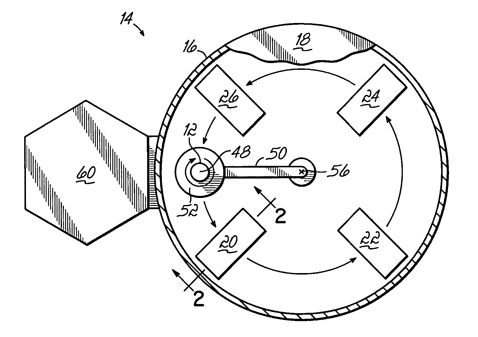
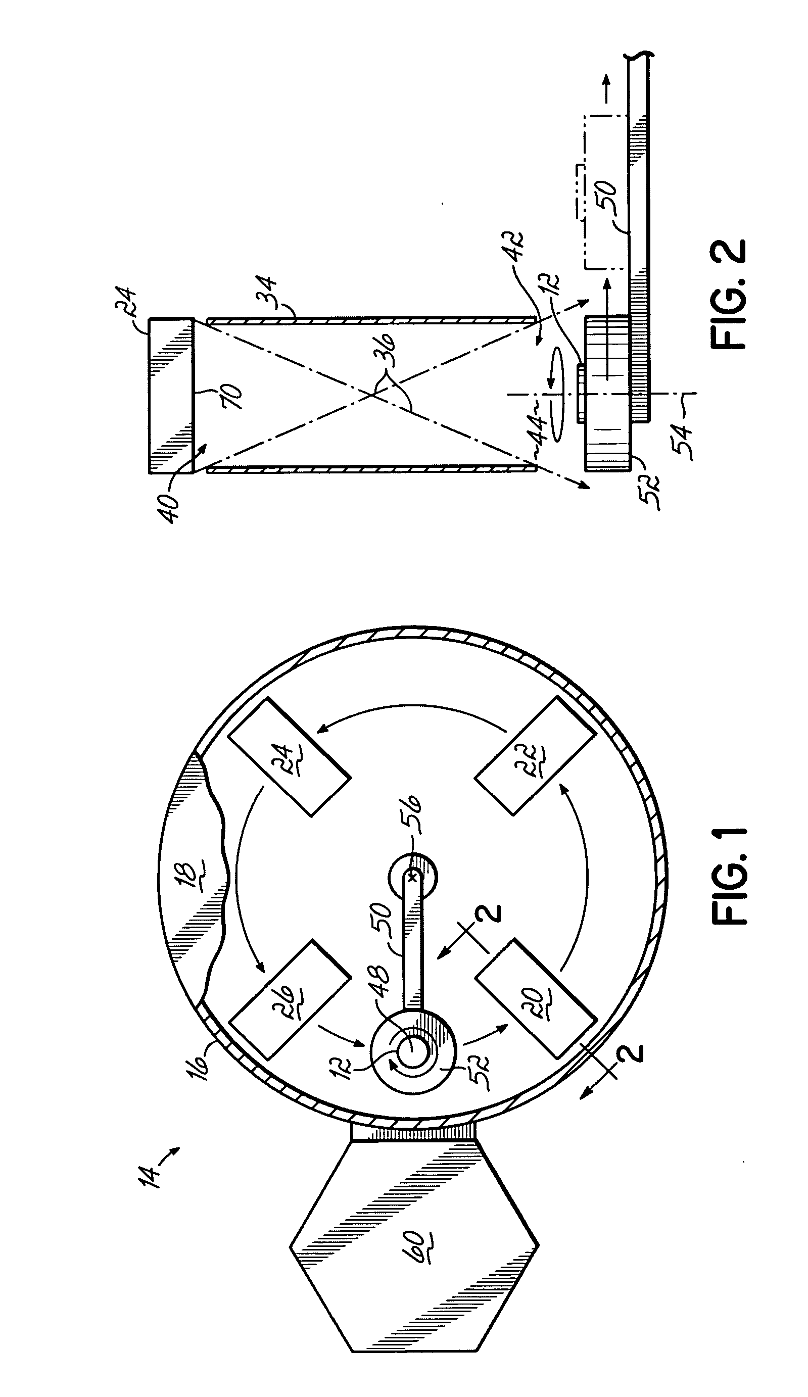
[0021] In accordance with an embodiment of the invention, as best shown in FIGS. 1-3, a method of sputter depositing an alloy 10 on a substrate 12 by planetary sputter deposition techniques includes providing a PVD module, or apparatus 14, having a vacuum chamber 16 and a chamber lid 18 (shown in partial) defining an evacuable or controlled atmosphere volume. The vacuum chamber 16 is provided with four targets 20, 22, 24 and 26. However, it is contemplated that the chamber 16 may hold up to about ten targets or more. The Nexus PVD-10 planetary process module available from Veeco Instruments, Inc. of Woodbury, N.Y., which is adapted to hold up to ten source targets, is one suitable type apparatus 14 for sputter depositing the alloy 10 on the substrate 12 in accordance with the method of the present invention. In addition, U.S. Pat. No. 5,795,448, which is hereby incorporated by reference herein in its entirety, describes the general operation of planetary process modules or devices. ...


PUM

PropertyMeasurementUnit
Fractionaaaaaaaaaa
Fractionaaaaaaaaaa
Fractionaaaaaaaaaa

Abstract

An improved planetary sputter deposition method for sputter depositing an alloy on a substrate wherein the sputter deposited amount, or thickness, of a specific material of the alloy can be controlled so that different substrates can be provided with an alloy having a different composition, i.e. having different percentages of the same materials, thus, reducing the costs of stockpiling multiple alloy targets. The method generally includes providing a substrate and a plurality of targets with each of the plurality of targets being composed of one or more magnetic materials. The targets are sputtered, in sequence, to deposit each of the materials of the plurality of targets on the substrate to provide at least one laminate defining an alloy.

Description

FIELD OF THE INVENTION [0001] The present invention relates to physical vapor deposition (PVD) for processing substrates like semiconductor wafers and data storage components and, more particularly, to using planetary sputter deposition methods for depositing a plurality of layers of magnetic material to form an alloy on such substrates. BACKGROUND OF THE INVENTION [0002] Physical vapor deposition (PVD) modules or tools generally are used in the manufacture of sensor elements, for example, for giant magnetoresistance (GMR) and tunneling magnetoresistance (TMR) read / write heads for the data storage industry and similar devices. With PVD, typically thin layers or films of metal are stacked on a substrate using a sputtering system, which includes a vacuum chamber having a cathode including a source target. During the sputtering process, material is removed from the source target and subsequently deposited on the substrate to form one or more layers of a desired thickness. It is also de...

Claims


Application Information

Patent Timeline
IPC IPC(8): C23C14/00
CPCC23C14/165C23C14/352
Inventor LEE, CHIH-LINGDEVASAHAYAM, ADRIANMAO, MINGHU, CHIH-CHINGIP, VINCENTSFERLAZZO, PIERO
Owner VEECO INSTR
Learn More