Rotor of rotary electric machine

a rotary electric machine and rotor technology, applied in the direction of rotating magnets, synchronous machines with stationary armatures, magnetic circuit rotating parts, etc., can solve the problems of increasing resistance, windage loss, increasing resistance, etc., to increase the total output of the alternator, reduce leakage magnetic flux, and increase the magnetic flux of the magnetic poles

Inactive Publication Date: 2007-03-01
DENSO CORP
View PDF6 Cites 30 Cited by
  • Summary
  • Abstract
  • Description
  • Claims
  • Application Information

AI Technical Summary

Benefits of technology

[0026] According to another aspect of the present invention, a permanent magnet is accommodated in each penetrate hole or each concave part in order to increase the magnetic flux of the magnetic poles. It is thereby possible to reduce the leakage magnetic flux by magnetically saturating the connection part and to increase the total output of the alternator.
[0027] According to another aspect of the present invention, because each magnetic pole part has a partial cylindrical shape and each connection part has a flat shape on the outer surface of the magnet-pole cylindrical portion, it is thereby possible to smoothly change the magnetic flux by gradually changing the outer diameter of the connection part. This smooth change of the magnetic flux can reduce magnetic noise generated according to the change of the magnetic flux. In addition, because the sectional area of the connection part is reduced in the circumference direction, it is possible to reduce the leakage
[0028] According to another aspect of the present invention, because the connection part has a weak magnetic characteristic when compared with that of the magnetic pole parts, it is thereby possible to reduce the leakage magnetic flux flowing through the connection part in the circumference direction. This increases the output of the alternator.
[0029] According to another aspect of the present invention, the connection parts are made of non-magnetic material. It is thereby possible to reduce the leakage magnetic flux drastically. Further, it is acceptable to form the connection parts with non-magnetic thin sheets laminated in the axis direction or to form them with thin sheets laminated in the axis direction. It is further possible to form the connection parts with an ingot-shape material instead of the lamination structure.
[0030] According to another aspect of the present invention, each connection part in the magnetic-pole cylindrical portion is pressed between the adjacent magnetic pole parts of soft magnetic characteristic in the axis direction, and the magnetic pole parts and the connection parts are fixed and mated in the circumference direction. It is thereby possible to have different magnetic characteristics of the magnetic pole parts and the connection parts easily, and to form the magnetic pole parts and the connection parts in one body. Because each connection part is applicable shiftable to the adjacent magnetic pole parts in the axis direction, it is easily possible to absorb the dimension tolerance or margin easily.
[0031] According to another aspect of the present invention, a part of each disk portion has a partial cylindrical surface whose outer diameter is approximately equal to that of each magnet pole part in the magnet-pole cylindrical portion. This partial cylindrical surface of the disk portion serves as a magnetic pole surface. The magnetic flux is transferred through this magnetic pole surface, the magnet-pole cylindrical portion, and the stator core. It is thereby possible to reduce the dimension of the magnetic-pole cylindrical portion in the axis direction and to increase deformation function of the magnetic-pole cylindrical portion in the axis direction because a part of the magnetic flux flows to the stator core through the disk portion.

Problems solved by technology

Such an ordinary Lundell type rotor core involves a drawback to generate large wind noise and to cause windage loss while the rotor core rotates at a high speed rotation because the claw poles of the pole core are exposed in the radial direction of the field coil in the outer space of the field coil wound on the boss portion of the rotor.
However, the magnetic-pole cylindrical portion in the Lundell type rotor core disclosed in the prior document, the Japanese patent laid open publication No. 2002-247815, involves a drawback that increases a space in an electromagnetic circuit in an electric rotary machine, and further increases an reluctance (or a magnetic resistance) and amount of a field current because a penetrate direction of magnetic flux is approximately equal to the direction of the laminated magnetic steel sheets.
Further, this prior technique involves a drawback to decrease a stiffness of the rotor core.
Further, the conventional technique, the Japanese patent laid open publication No. 2005-27415, has a manufacturing limitation of a small allowable-dimension tolerance of each of both the side cores and the magnetic-pole cylindrical portion and a difficulty to satisfy a necessary manufacturing accuracy because its Lundell type rotor core is made of soft magnetic core of an ingot shape.
This drawback increases the manufacturing cost of the Lundell type rotor core.
Such a presence of the gap decreases the stiffness of the rotor core and also increases the necessary amount of a field current because of increasing the reluctance (or the magnetic resistance).

Method used


Image

  • Rotor of rotary electric machine
  • Rotor of rotary electric machine
  • Rotor of rotary electric machine

Examples


embodiment

[0046] A description will be given of the configuration of a rotor core of a rotor in a vehicle alternator which adopts a Lundell type rotor core having a magnetic-pole cylindrical portion mounted on a vehicle alternator according to an embodiment of the present invention.

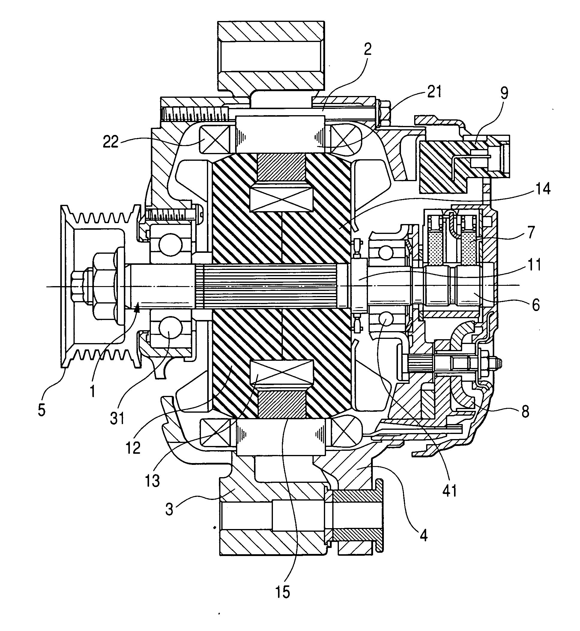
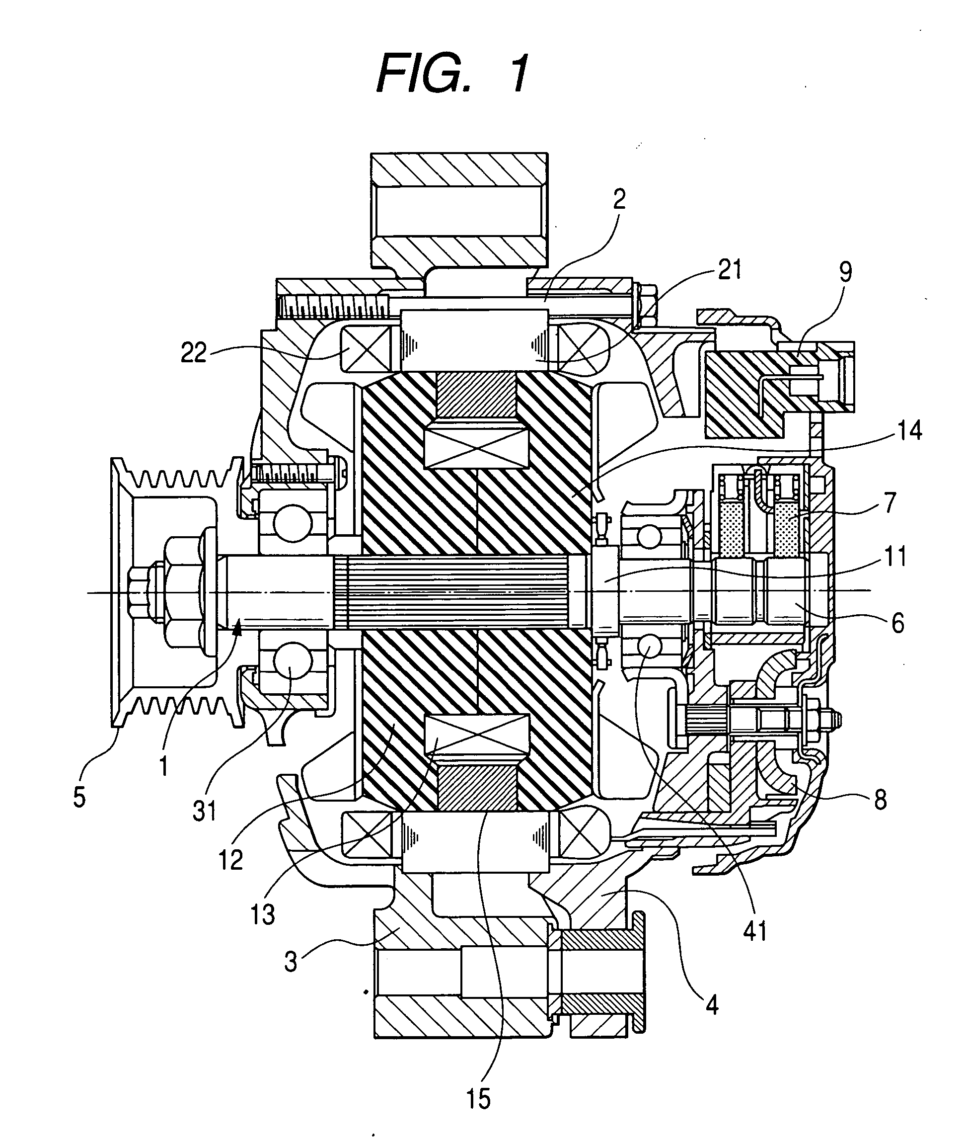
[0047]FIG. 1 is a sectional diagram of the vehicle alternator in an axis direction with an improved mechanism of the Lundell type rotor core with the magnetic-pole cylindrical portion according to the embodiment of the present invention.

[0048] The vehicle alternator equipped with the Lundell type rotor core and the magnetic-pole cylindrical portion shown in FIG. 1 has a rotor 1, a stator 2, a front frame 3, a rear frame 4, a pulley 5, a slip ring 6, a brush mechanism 7, a rectifier 8, and a regulator 9. The magnetic-pole cylindrical portion has a hollow cylindrical shape (for example, see FIG. 2, FIG. 5).

[0049] The stator 2 has a stator coil wound on a stator core 21 and fixed to the inner circumference surfaces...

first modification

(First Modification)

[0072] A description will now be given of another configuration of the magnetic-pole cylindrical portion in the Lundell type rotor core of the rotor in the vehicle alternator with reference to FIG. 5.

[0073]FIG. 5 is an oblique diagram showing another configuration of the magnetic-pole cylindrical portion 515. The magnetic-pole cylindrical portion 515 as a modification has the configuration in which a permanent magnet 155 of a square pole shape is inserted into each penetrate hole 150. As well known, the side surface of the permanent magnet 155 in the circumference direction is the magnetic surface in order to increase the magnetic pole. By this configuration using the permanent magnets 155, it is possible to increase the output of the alternator of the Lundell type rotor core without increasing the entire volume thereof.

second modification

(Second Modification)

[0074] A description will now be given of another configuration of the Lundell type rotor core of the rotor in the vehicle alternator with reference to FIG. 6.

[0075]FIG. 6 is an oblique diagram showing another configuration of the magnetic-pole cylindrical portion. As shown in FIG. 6, the outer peripheral surface “S1” of each connection part 653 at the boundary part 652 in the magnetic-pole cylindrical portion 615 is formed with a flat shape. This configuration can reduce the amount of leakage magnetic flux because the sectional area of the magnetic path in the connection part 653. In addition, because the magnitude flux in the stator core is smoothly changed through the connection part 653, it is possible to reduce magnetic noise caused by the change of the magnetic flux. In addition, because of the reduction of the bending stiffness of the connection part 653 in the axis direction, it is possible to easily deform the connection part 653 toward the axis direct...


PUM


Abstract

A Lundell type rotor core with a pair of side cores and a magnetic-pole cylindrical portion has a structure in which the magnetic-pole cylindrical portion is mated between both the side cores (also referred to as “pole cores”) in a radial direction at an outside of a field coil wound on a boss portion in the side cores. The magnetic-pole cylindrical portion is made of plural magnetic steel sheets laminated in the axis direction, and is easily deformed rather than both the side cores. The easy deformation characteristic of the magnetic-pole cylindrical portion prevents generation of a gap during the assembling process of the magnetic-pole cylindrical portion and the side cores. Without paying strict dimension control of the components for the rotor core, it is easily possible to prevent any generation of a gap between the side cores and the magnetic-pole cylindrical portion while assembling. It is thereby possible to prevent a deterioration of a magnetic flux flowing in the rotor core.

Description

CROSS-REFERENCE TO RELATED APPLICATIONS [0001] This application is related to and claims priority from Japanese Patent Application No. 2005-249749 filed on Aug. 30, 2005, the contents of which are hereby incorporated by reference. BACKGROUND OF THE INVENTION [0002] 1. Field of the invention [0003] The present invention generally relates to an improved rotor of a rotary electric machine such as a vehicle alternator to be driven by an internal combustion engine of a vehicle, for example. [0004] 2. Description of the Related Art [0005] The Lundell type rotor core of a rotor in an ordinary available vehicle alternator has a boss portion, disk portions (or pole cores), and a pair of pole cores. Through the boss portion a field magnetic flux flows in the axis direction of the rotor in the inside area of a field coil and in the radial direction of the field coil. The disk portions, that are formed extended from both the outer end of the boss portion in the axis direction toward the outer e...

Claims


Application Information

Patent Timeline
Patent Type & Authority Applications(United States)
IPC IPC(8): H02K1/22
CPCH02K21/044
Inventor OOIWA, TOORU
Owner DENSO CORP
Why Eureka
Try Eureka