Organic electroluminescent device, cover plate of organic electroluminescent device, and method for fabricating cover plate

Inactive Publication Date: 2007-03-01
CHUNGHWA PICTURE TUBES LTD
View PDF7 Cites 5 Cited by
  • Summary
  • Abstract
  • Description
  • Claims
  • Application Information

AI Technical Summary

Benefits of technology

[0012] Since the bonding region of the substrate is cleaned after the desiccant layer is formed, the present invention provides higher adhesive s

Problems solved by technology

In general, since the organic functional material layer is easily deteriorated in presence of moisture, a desiccant layer is formed on a cover plate of the organic el

Method used


Image

  • Organic electroluminescent device, cover plate of organic electroluminescent device, and method for fabricating cover plate
  • Organic electroluminescent device, cover plate of organic electroluminescent device, and method for fabricating cover plate
  • Organic electroluminescent device, cover plate of organic electroluminescent device, and method for fabricating cover plate

Examples


Example

[0016] Reference will now be made in detail to the present preferred embodiments of the invention, examples of which are illustrated in the accompanying drawings. Wherever possible, the same reference numbers are used in the drawings and the description to refer to the same or like parts.

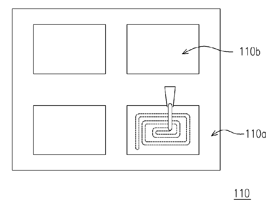
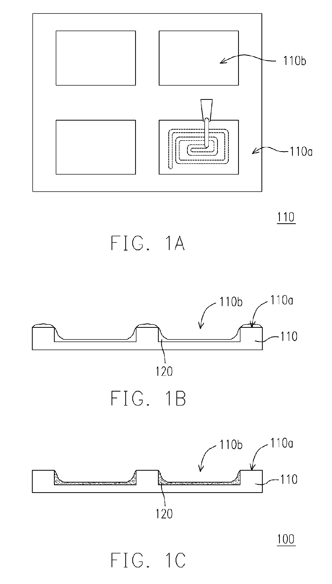
[0017]FIG. 1A through 1E is schematic views illustrating a method for fabricating an organic electroluminescent device according to a preferred embodiment of the present invention. Referring to FIG. 1A, a substrate 110 is provided, wherein the material of the substrate 110 may be glass or metal. In addition, the substrate 110 has a concave 110b and a bonding region 110a surrounding the concave 110b. It should be noted that a cleaning process can be selectively performed first, wherein the cleaning process may comprise the steps of wet cleaning, vacuum drying, and dry cleaning in sequence. The step of dry cleaning is performed by using oxygen plasma or excimer laser.

[0018] Then, a liquid-state desi...


PUM


Abstract

A method for fabricating a cover plate of an organic electroluminescent device comprising the following steps is provided. First, a substrate is provided, wherein the substrate has a bonding region. Then, a liquid-state desiccant layer is formed on the substrate, wherein the liquid-state desiccant layer is surrounded by the bonding region. Next, the liquid-state desiccant layer is cured to form a desiccant layer. Then, the bonding region of the substrate is cleaned. As mentioned above, the contaminants on the bonding region can be drastically reduced. Moreover, an organic electroluminescent device and a cover plate thereof are also provided.

Description

BACKGROUND OF THE INVENTION [0001] 1. Field of the Invention [0002] The present invention generally relates to a light-emitting device. More particularly, the present invention relates to an organic electroluminescent device, a cover plate of the organic electroluminescent device, and a method for fabricating the cover plate. [0003] 2. Description of Related Art [0004] Organic electroluminescent device (OELD) utilizes the self-illuminating property of an organic functional material to illuminate an image. According to the molecular weight of the organic functional material, the OELD can be classified into small molecule organic electroluminescent device (SM-OELD) and polymer electroluminescent device (PELD). The light-emitting structure of both types of OELD comprises a pair of electrodes and an organic functional material layer sandwiched between the two. When a DC voltage is applied to the electrodes, holes are injected from the anode into the organic functional material layer whi...

Claims


Application Information

Patent Timeline
IPC IPC(8): H05B33/04
CPCH01L51/5237H10K50/846H10K50/841H10K71/851
Inventor KUAN, YUNG-CHIATAI, WEI-JEN
Owner CHUNGHWA PICTURE TUBES LTD
Why Eureka
Try Eureka