
Distributed image processing for medical images

Active Publication Date: 2007-03-01
GENERAL ELECTRIC CO
View PDF20 Cites 105 Cited by
  • Summary
  • Abstract
  • Description
  • Claims
  • Application Information

AI Technical Summary

Benefits of technology

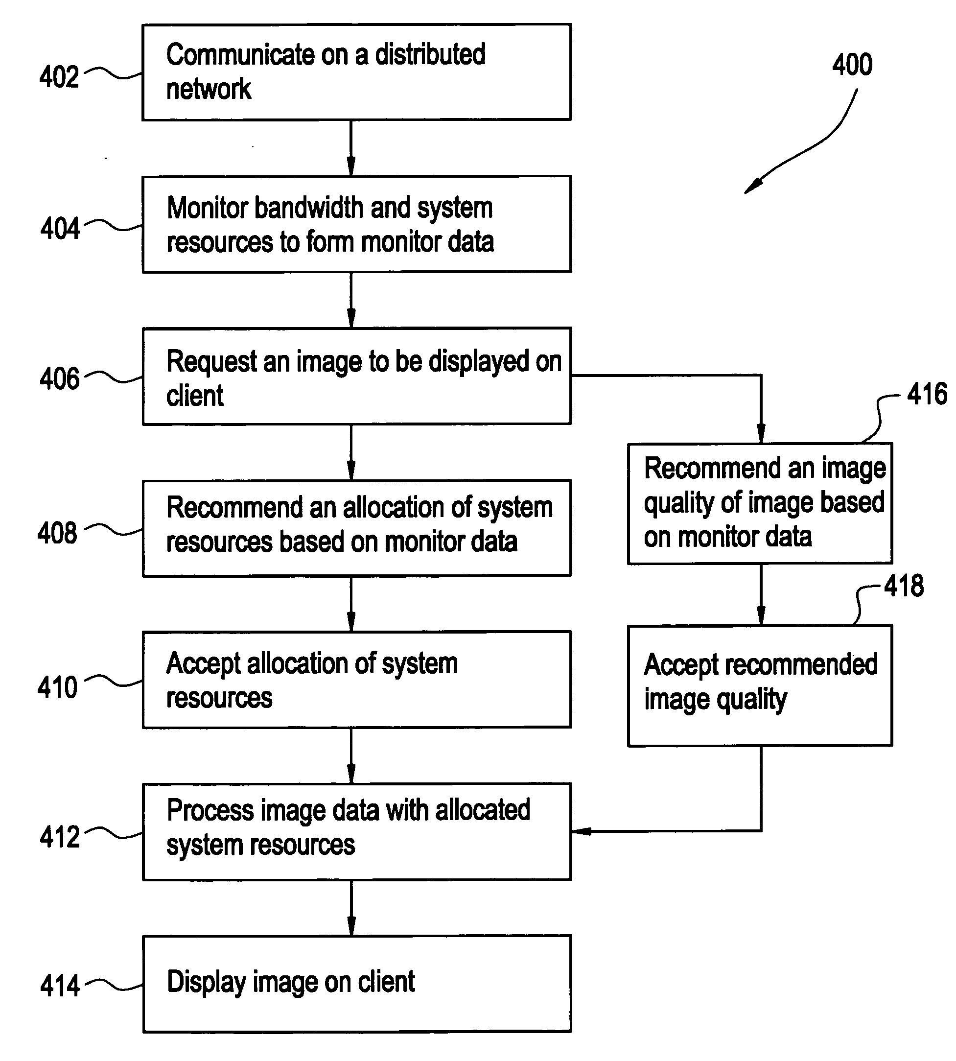
[0020] Certain embodiments of the present invention provide a computer-readable storage medium including a set of instructions for a computer, the set of instructions comprising: a monitoring routine for monitoring system resources of a distributed network comprising a client and a server, and a bandwidth of a communications channel linking the client and the server, wherein the monitoring routine generates monitor data; a requesting routine for requesting display of a two dimensional image at the client, the two dimensional image formable by processing three dimensional image data storable on the server; and a recommending routine for recommending an image quality of the two dimensional image, and an allocation of the system resources on the distributed network to display the two dimensional image at the client based at least on the monitor data. In an embodiment, the system resources comprises a processing load of the server and a processing speed of the client. In an embodiment, the allocation of the system resources comprises at least one of: an allocation of the system resources corresponding to the server for 3D image processing and 2D image processing; an allocation of the system resources corresponding to the client for 3D image processing and 2D image processing; and an allocation of the system. In an embodiment, resources corresponding to the server for 3D image processing and the system resources corresponding to the client for 2D image processing. In an embodiment, the recommendation routine recommends an allocation of allocation of the system resources corresponding to the server for 3D image processing and 2D image processing based at least in part on the monitor data indicating the server is substantially unloaded. In an embodiment, the recommendation routine recommends an allocation of the system resources corresponding to the client for 3D image processing and 2D image processing based at least in part on the monitor data indicating the server is substantially loaded and the bandwidth of the communications channel is capable of communicating the three dimensional image data from the server to the client without substantial delay. In an embodiment, the recommendation routine recommends an allocation of the system resources corresponding to the server for 3D image processing and the system resources corresponding to the client for 2D image processing based at least in part on the monitor data indicating the server is substantially loaded and the bandwidth of the communications channel is capable of communicating the three dimensional image data from the server to the client with substantial delay.

Problems solved by technology

Solutions that are applicable for synthetic modeling, however, may prove less practical for medical imaging.
In other words, medical images may not readily be decomposed into constituent parts.
Thus, decomposition solutions may not be practical for distributed imaging of medical images.
Additionally, adaptive techniques that rely on feedback may fail to efficiently allocate distributed resources at the outset of a processing task.
In other words, feedback-reliant systems may eventually gravitate towards an efficient solution, but may inefficiently allocate resources at the beginning of a task.
Thus, it may not be possible to efficiently determine which particular factor may be influencing feedback information.
A clinician may not be able to view a 3D medical image data volume without further processing.
In addition, such techniques may also significantly reduce the size of data.
However, techniques such as MPR, MIP, and VR may consume a substantial amount of processing resources.
If processing resources are not readily available, imaging performance may become slow or degraded.
Similarly, if a network has relatively low bandwidth, it may take a relatively long time to transfer 3D image data across the network.
Moreover, other factors such as image quality of both 3D data and processed 2D data may impact the performance of an image display system.

Method used


Image

  • Distributed image processing for medical images
  • Distributed image processing for medical images
  • Distributed image processing for medical images

Examples


Embodiment Construction

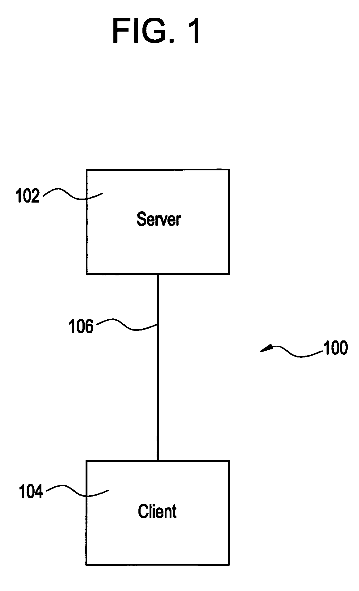
[0030]FIG. 1 shows a block diagram of a distributed network 100 according to an embodiment of the present application. Distributed network 100 may include a server 102, a client 104, and a communication pathway 106. The communication pathway 106 has an associated bandwidth. The bandwidth of communication pathway 106 may be uniform across the entire communication pathway 106, or it may vary along various segments. For example, a communication pathway 106 may include a combination of various types of networks having various bandwidths, such as a copper wire twisted-pair network and an optical network. A communication pathway 106 may include a local area network (LAN), wide area network (WAN), wired network, wireless network, optical network, and the like, or any combination thereof. Similarly, a communication pathway 106 may include various network elements, such as routers, repeaters, switches, hubs, splitters, couplers, intermediary computers, or the like.

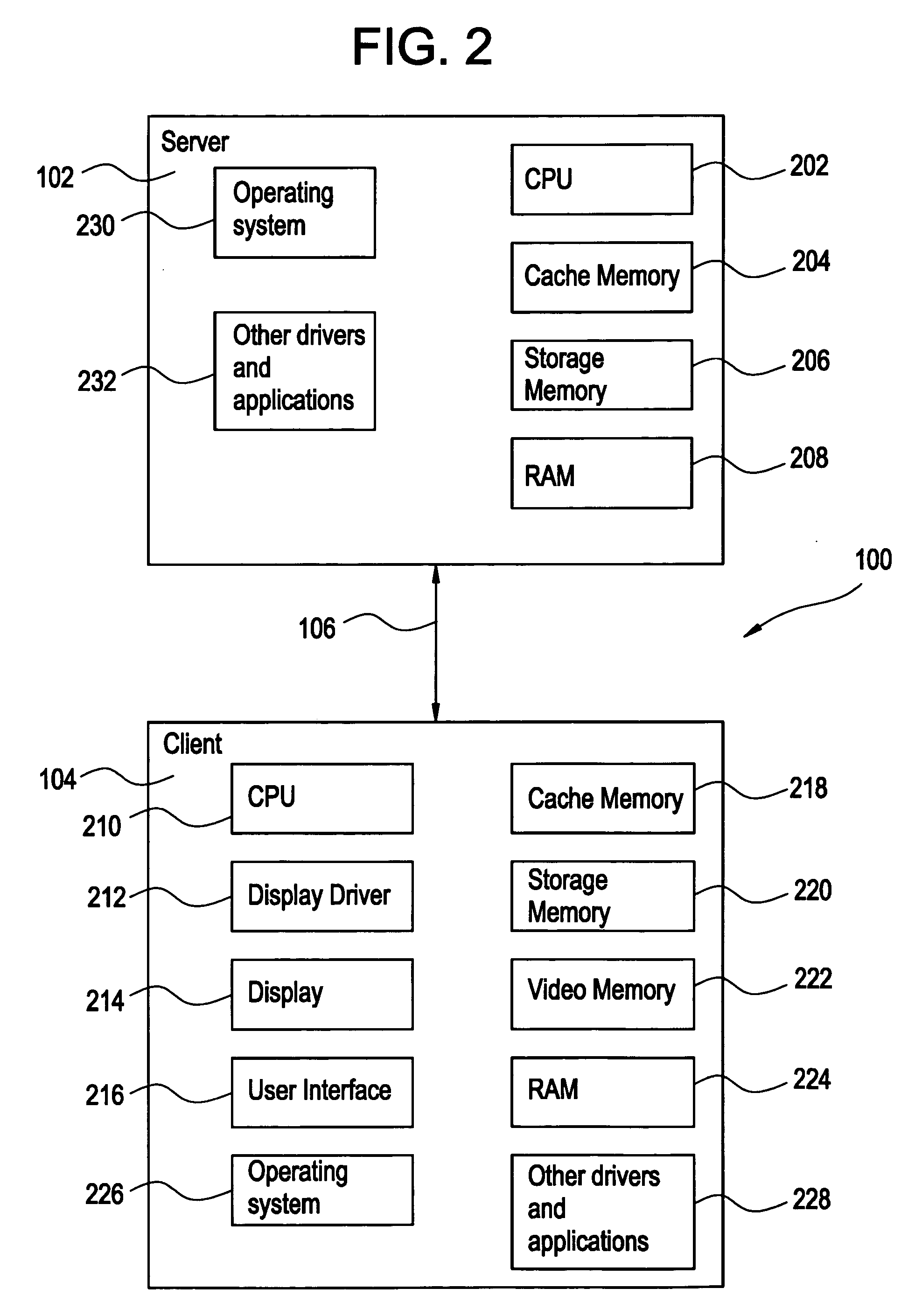
[0031]FIG. 2 shows a block...


PUM


Abstract

Certain embodiments of the present invention provide a method of medical image processing on a distributed network including: communicating on a distributed network comprising a server, a client, and a communications pathway having a bandwidth, wherein the distributed network comprises system resources related to the server, the client, and the communications pathway; monitoring the system resources and the bandwidth with at least one process monitor to generate monitor data; and recommending an allocation of at least a portion of the system resources for processing three dimensional image data to form two dimensional image data displayable on the client, wherein the allocation is based at least in part on the monitor data.

Description

BACKGROUND OF THE INVENTION [0001] Embodiments of the present application relate generally to distributed processing. Particularly, certain embodiments relate to allocating medical image data processing between a client and a server to display an image on the client. [0002] The proliferation of computers in the modern era has been accompanied by a proliferation of computer networks. Computer networks include local area networks (LANs), wide area networks (WANs), wired networks, wireless networks, optical networks, and the like, or any combination thereof. Networks allow for communications between individual computers on the network. [0003] In addition to sharing data, computer networks also facilitate the sharing of computer resources. In a resource-sharing network, the overall amount of resources available to an individual computer is enhanced. A resource-sharing network may also be called a distributed network, because the overall resources available on the network are distributed...

Claims


Application Information

Patent Timeline
IPC IPC(8): G06F3/12G06T15/00G06T15/08
CPCG06T1/20H04L43/0817H04L43/0811G06T2200/16
Inventor MUSSACK, CHRISTOPHER JOSEPHYAN, LITAOJONES, CHERYL RUTHSIROHEY, SAAD AHMEDMACK, DAVID CHARLES
Owner GENERAL ELECTRIC CO
Learn More