Information transfer and interrupt event scheduling scheme for a communications transceiver incorporating multiple processing elements

a technology which is applied in the field of information transfer and interrupt event scheduling scheme of communications transceivers, can solve the problems of constrained downlink and uplink transmit power control loops

Inactive Publication Date: 2007-12-11
COMSYS COMM & SIGNAL PROC
View PDF13 Cites 19 Cited by
  • Summary
  • Abstract
  • Description
  • Claims
  • Application Information

AI Technical Summary

Benefits of technology

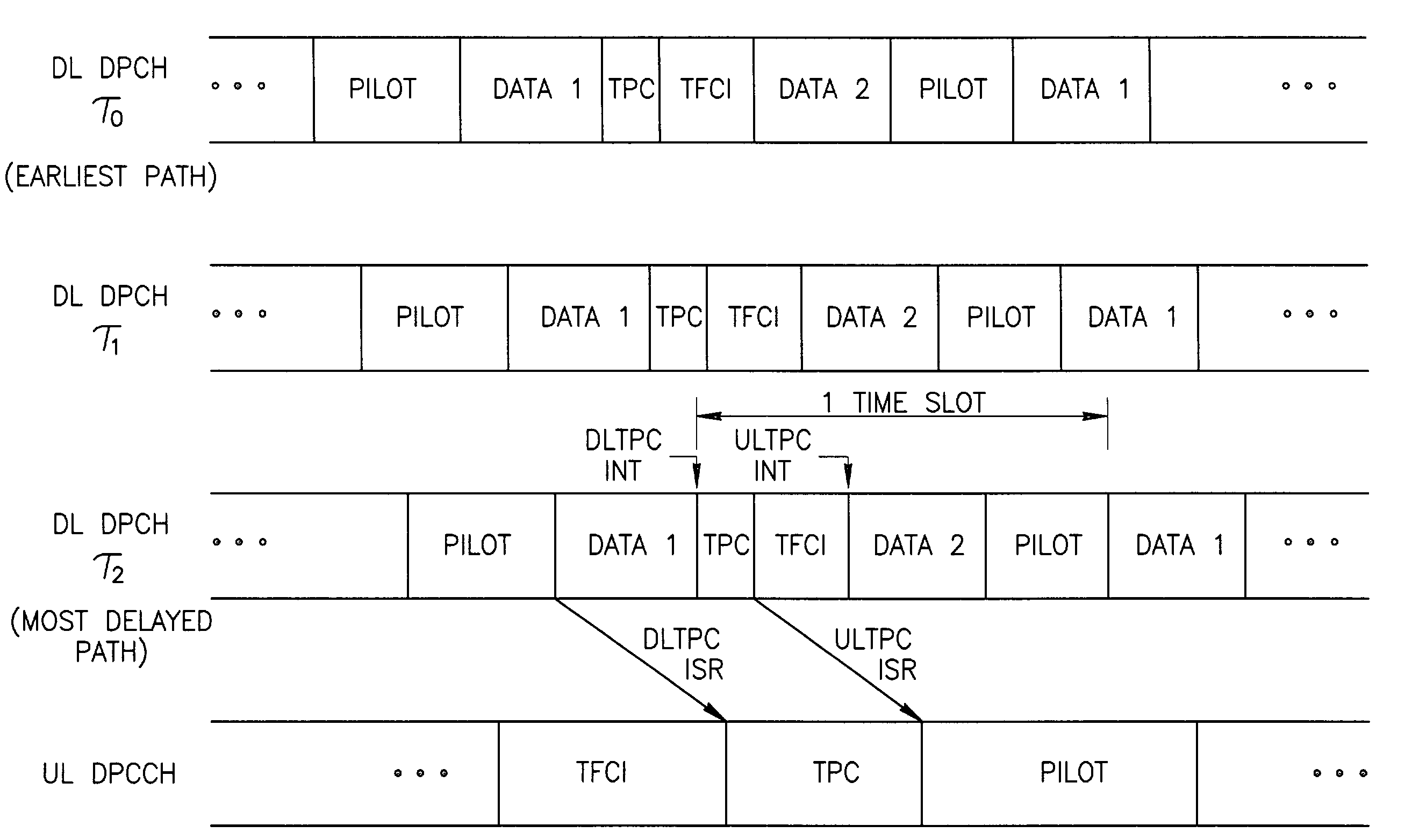
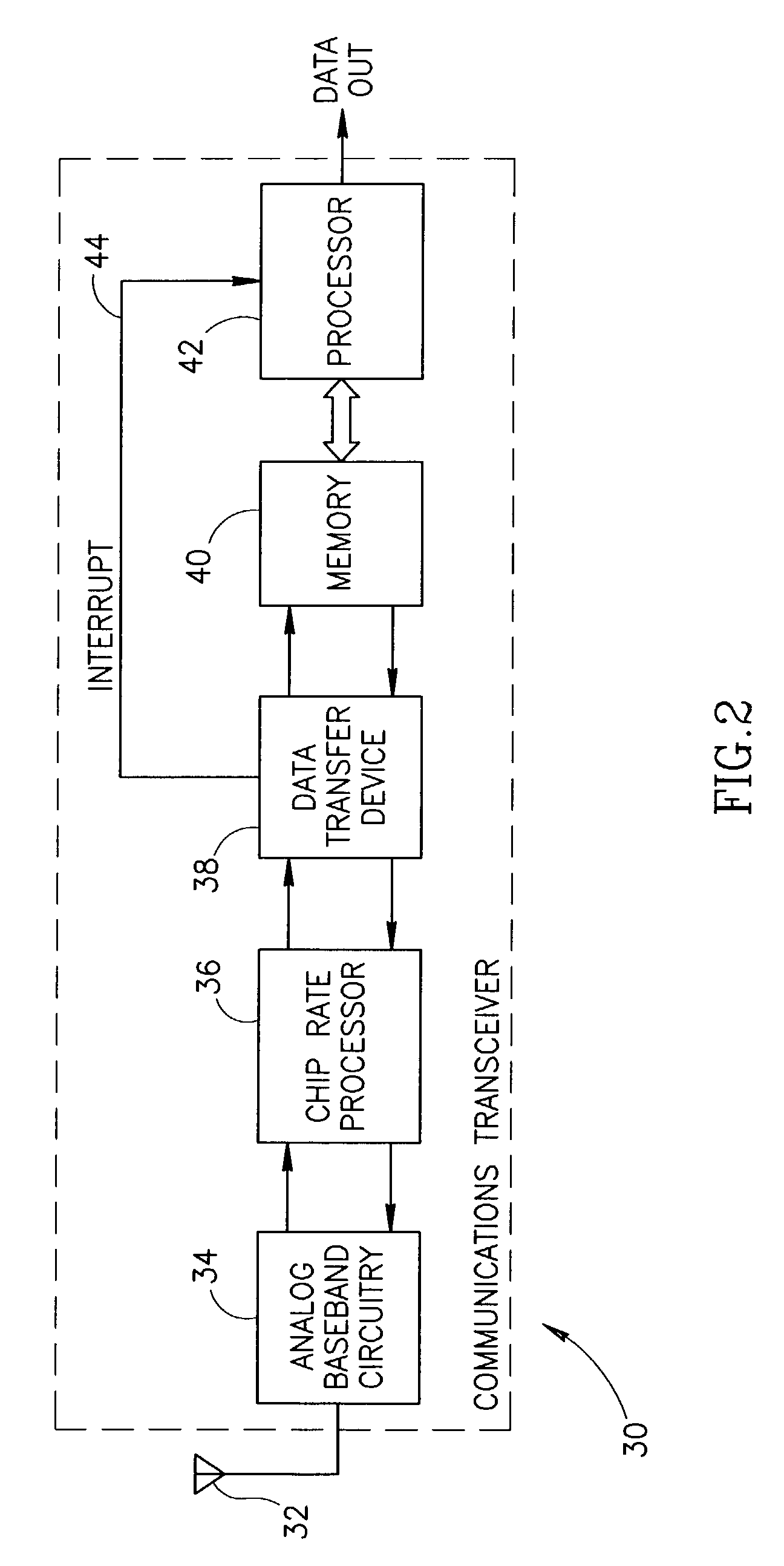
[0027]There is further provided in accordance with the invention, a Universal Mobile Terrestrial Service (UMTS) User Equipment (UE) compatible communications transceiver comprising analog baseband processor, a chip rate processor comprising a rake receiver having a plurality of fingers, a memory adapted to store symbols output of the plurality of fingers, data transfer means operative to effect the transfer of symbols from the plurality of fingers to the memory, a processor coupled to the memory and software means adapted to be executed on the processor for: selecting during each time slot a finger having maximal delay as an interrupt timing reference, configuring the data transfer means during each time slot to generate a first interrupt upon transfer of a first predetermined number of downlink dedicated physical channel (DL-DPCH) pilot symbols determined in accordance with the interrupt timing reference, configuring the data transfer means during each time slot to generate a second interrupt upon transfer of a second predetermined number of downlink dedicated physical channel (DL-DPCH) Transmit Power Control (TPC) symbols determined in accordance with the interrupt timing reference, performing symbol rate processing on the contents of the memory.

Problems solved by technology

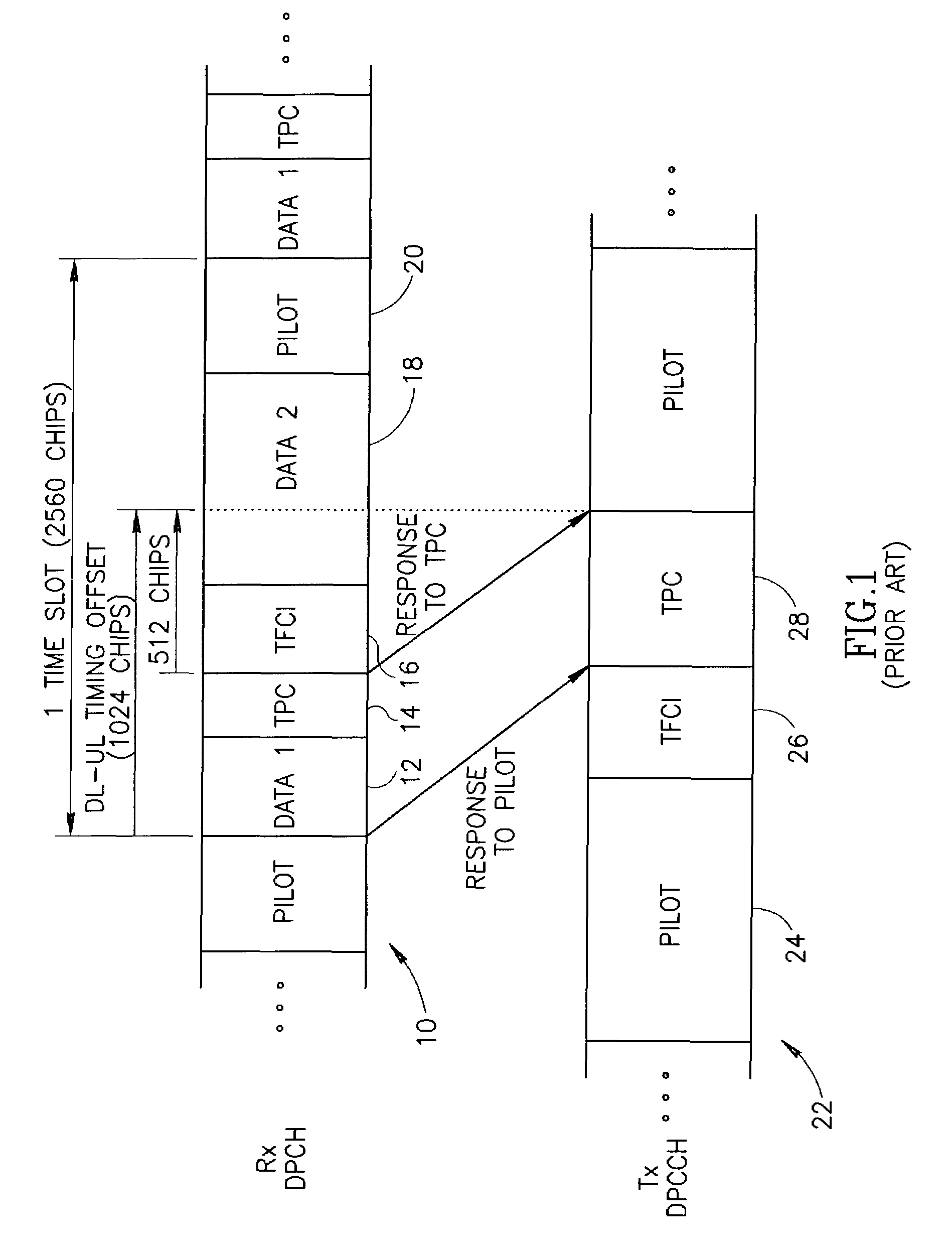
From a scheduling perspective, however, both downlink and uplink transmit power control loops are constrained by the same limitation, namely the structure, format and timing separation of the DL-DPCH and UL-DPCCH time slot data fields.

Method used


Image

  • Information transfer and interrupt event scheduling scheme for a communications transceiver incorporating multiple processing elements
  • Information transfer and interrupt event scheduling scheme for a communications transceiver incorporating multiple processing elements
  • Information transfer and interrupt event scheduling scheme for a communications transceiver incorporating multiple processing elements

Examples


Embodiment Construction

Notation Used ThroughoutThe following notation is used throughout this document.TermDefinition3GPPThird Generation Partnership ProjectASICApplication Specific Integrated CircuitBLERBlock Error RateBPFBand Pass FilterCDMACode Division Multiple AccessCNCore NetworkCPUCentral Processing UnitDL-DPCHDownlink Dedicated Physical ChannelDLTPCDownlink Transmit Power ControlDMADirect Memory AccessDPCCHDedicated Physical Control ChannelDPCHDedicated Physical ChannelDPDCHDedicated Physical Data ChannelDPRAMDual Port Random Access MemoryDSPDigital Signal ProcessorFIFOFirst In First OutFPGAField Programmable Gate ArrayIFIntermediate FrequencyISRInterrupt Service RoutineMRCMaximal Ratio CombiningRAMRandom Access MemoryRFRadio FrequencyROMRead Only MemorySIRSignal to Interference RatioTFCITransport Format Combination IndicatorTPCTransmit Power ControlUEUser EquipmentUL-DPCHUplink Dedicated Physical Control ChannelULTPCUplink Transmit Power ControlUMTSUniversal Mobile Terrestrial ServiceUTRANUnivers...


PUM


Abstract

A real-time optimizing information transfer and interrupt event scheduling scheme for a communications transceiver incorporating multiple processing elements. The scheme is particularly applicable for use in UMTS based communications transceivers, i.e. W-CDMA transceivers adapted for User Equipment (UE). The interrupt scheduling scheme of the present invention is operative to perform the scheduling of interrupts used to configure a data transfer device to effect the timely transfer of data from a hardware based chip rate processor to a memory buffer for subsequent processing by software running on a DSP or other processor platform.

Description

REFERENCE TO RELATED APPLICATIONS[0001]This application is related to U.S. application Ser. No. 10 / 262,804, filed Oct. 1, 2002, entitled “Data Transfer Scheme In A Communications System Incorporating Multiple Processing Elements,” now U.S. Pat. No. 6,859,434, similarly assigned and incorporated herein by reference in its entirety.FIELD OF THE INVENTION[0002]The present invention relates generally to the area of communications transceivers and more particularly relates to an interrupt event scheduling scheme for optimizing information transfer between modules in a communications transceiver incorporating multiple processing elements.BACKGROUND OF THE INVENTION[0003]Mobile radio communication systems are currently under development to provide global mobility with a wide range of services including telephony, paging, messaging, and broadband including Internet access. The Third Generation Partnership Project (3GPP) formed for technical development of the W-CDMA standard has five main U...

Claims


Application Information

Patent Timeline
Patent Type & Authority Patents(United States)
IPC IPC(8): H04J13/02
CPCH04B1/7117H04W52/54H04B2201/70701H04W52/58H04W52/56
Inventor ERAN, ALONAVITAL, YANIVRESHEF, EHUD
Owner COMSYS COMM & SIGNAL PROC
Why Eureka
Try Eureka