Video comfort noise addition technique
- Summary
- Abstract
- Description
- Claims
- Application Information
AI Technical Summary
Benefits of technology
Problems solved by technology
Method used
Image
Examples
first embodiment
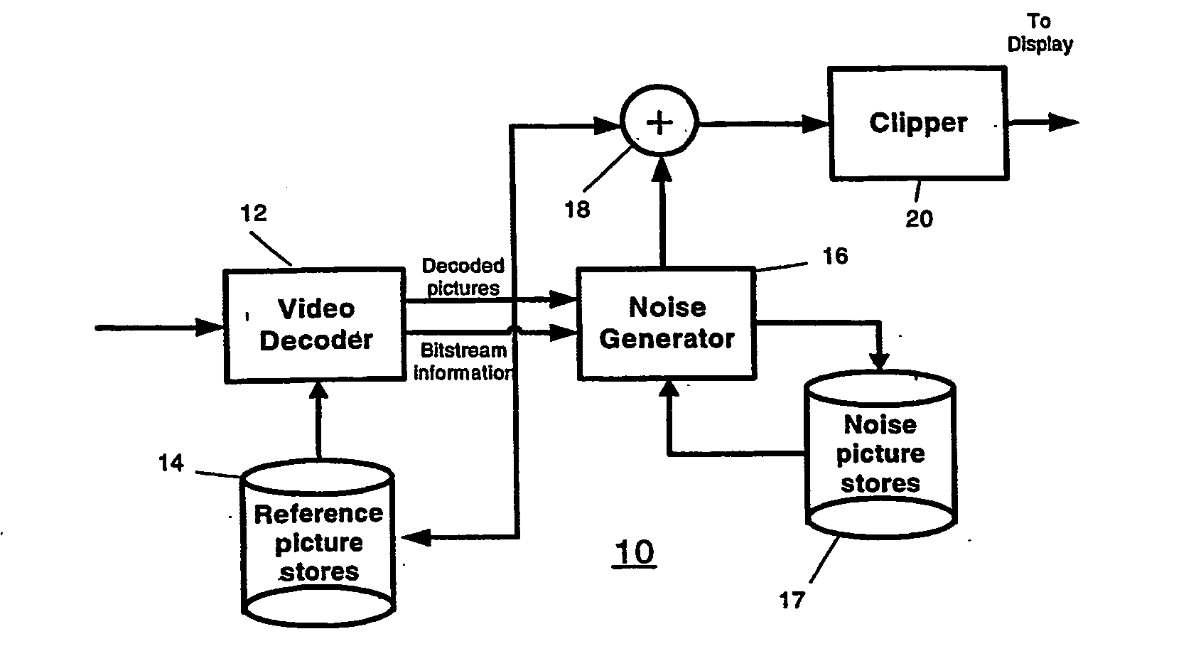
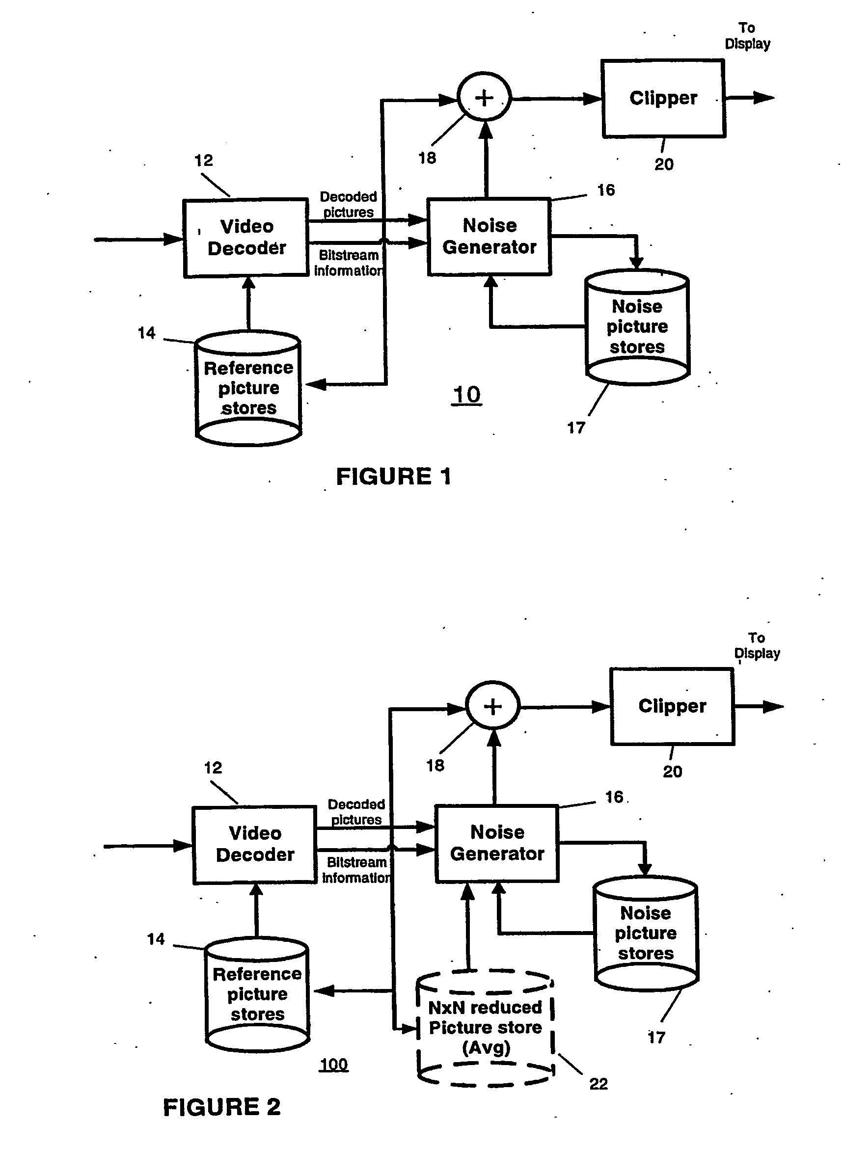
[0015]FIG. 1 depicts a block schematic diagram of a video decoder arrangement 10 for adding noise correlated to the luminance of at least a portion of the current picture in a manner compatible with Equation 2 to reduce artifacts. The decoder arrangement 10 includes a decoder 12 for decoding an incoming coded video stream. The design of decoder 12 depends on the compression format employed to code the incoming video stream. In a preferred embodiment, the incoming video stream undergoes compression using the well-known ITU / ISO H. 264 standard. Under such circumstances, the decoder 12 takes the form of a H.264 decoder known in the art. A reference picture store 14 stores pictures decoded by the decoder 12 for use by the decoder in decoding future pictures.
[0016] The decoder 12 supplies a noise generator 16 with both a decoded picture, as well as bit stream information contained in the decoded picture. The bit stream information output by the decoder 12 can include a quantization param...
second embodiment
[0020]FIG. 2 depicts a block schematic diagram of a video decoder arrangement 100 for adding large grain noise correlated to the luminance of at least a portion of the current picture. The decoder arrangement 100 includes many of the same elements as the decoder arrangement 10 of FIG. 1, and like reference numbers identify like elements. As compared to the decoder arrangement 10 of FIG. 1, the decoder arrangement 100 of FIG. 2 further includes a N×N reduced picture average store 22 coupled to the reference picture store 14. The picture store 22 typically stores N×N luma block average values. The average luma values stored in the picture store 22 allow the decoder arrangement to generate larger grain noise as discussed.
third embodiment
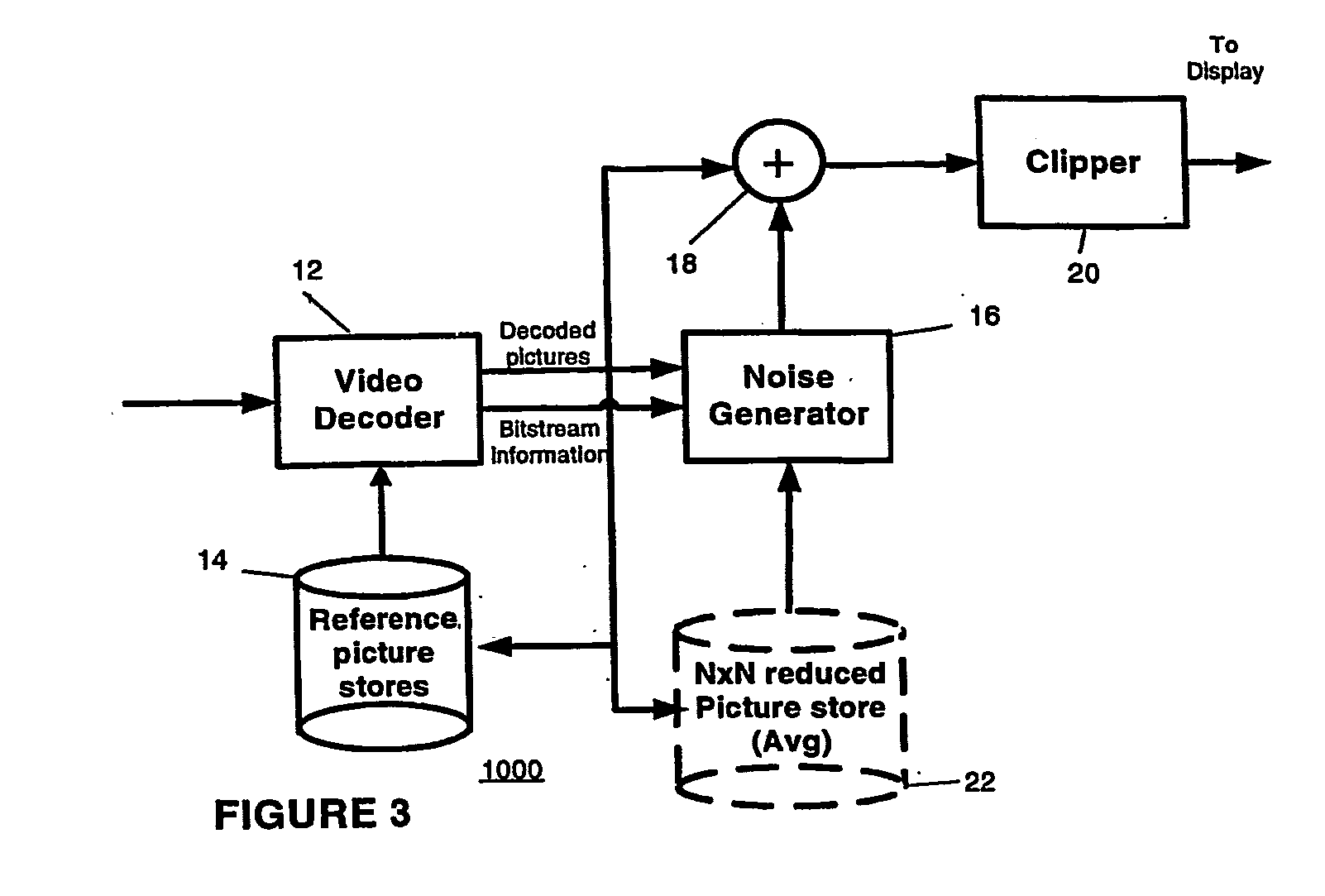
[0021]FIG. 3 depicts a block schematic diagram of a video decoder arrangement 1000 for adding large grain noise correlated to the luminance of at least a portion of the current picture. The decoder arrangement 1000 of FIG. 3 includes many of the same elements as the decoder arrangement 100 of FIG. 2, and like reference numbers identify like elements. As compared to the decoder arrangement 100 of FIG. 2, the decoder arrangement 1000 of FIG. 3 contains no noise picture store 17, but only the N×N reduced picture average store 22.
[0022] An alternative and considerably simpler process would be to generate the noise at a smaller resolution than that of the original image (e.g. half horizontal and vertical resolution), and then up sample the noise (e.g. using sample replication). Using the original or smaller resolution could also be decided based on the resolution of the original pictures (e.g. use same resolution for Standard Definition and lower definition material, while using lower re...
PUM
 Abstract
Description
Claims
Application Information
 - R&D
- Intellectual Property
- Life Sciences
- Materials
- Tech Scout
- Unparalleled Data Quality
- Higher Quality Content
- 60% Fewer Hallucinations
Browse by: Latest US Patents, China's latest patents, Technical Efficacy Thesaurus, Application Domain, Technology Topic, Popular Technical Reports.
© 2025 PatSnap. All rights reserved.Legal|Privacy policy|Modern Slavery Act Transparency Statement|Sitemap|About US| Contact US: help@patsnap.com


