Bi-directional fixating transvertebral body screws, zero-profile horizontal intervertebral miniplates, total intervertebral body fusion devices, and posterior motion-calibrating interarticulating joint stapling device for spinal fusion

a transvertebral body and screw technology, applied in the field of unique universal bidirectional screw system, can solve the problems of pseudoarthrose, prolonged recovery, excessive blood loss, etc., and achieve the effect of increasing the rostral and caudal segmental stress, facilitating strong solid fusion, and increasing the rate of re-operation

Inactive Publication Date: 2007-03-01
MOSKOWITZ FAMILY LLC
View PDF48 Cites 148 Cited by
  • Summary
  • Abstract
  • Description
  • Claims
  • Application Information

AI Technical Summary

Benefits of technology

[0010] The very advantage of trans-pedicular screws which facilitate a strong solid fusion by rigidly engaging all three spinal columns (anterior, middle and posterior), is the same mechanical mechanism whereby complete inflexibility of all columns is incurred thereby leading to increasing rostral and caudal segmental stress which leads to an increased rate of re-operation.
[0011] Transvertebral fusion also leads to far less muscle retraction, blood loss, and significant reduction in O.R. time. Thus the complication of pedicular screw pull-out and hence high re-operation rate associated with the current embodiment of flexible fusion pedicle screws / rods is obviated. The lumbosacral BDFT screws can be introduced via PLIF, TLIF or ALIF operative techniques. Although one can opt to supplement these screws with transpedicular screws there would be no absolute need for supplemental pedicle screw fixation with these operative techniques.

Problems solved by technology

Because of the poor blood supply of the transverse processes, issues still remained with pseudoarthroses.
Complications of pedicle screw placement include duration of procedure, significant tissue dissection and muscle retraction, misplaced screws with neural and / or vascular injury, excessive blood loss, need for transfusions, prolonged recovery, incomplete return to work, excess rigidity leading to adjacent segmental disease requiring further fusions and re-operations.
Complications of all current interbody fusion devices is their lack of coverage of the majority of the cross sectional area of the vertebral endplates and their potential for extrusion.
The recently described flexible fusion system which consists of flexible rods attached to transpedicular screws (Dionysis, Zimmer) suffers from a high pull-out rate, higher rate of re-operation than standard fusions, and does not rank high with patient satisfaction.
These advances, however, have not eliminated the possibility of plate dislodgement and screw back out / breakage.

Method used


Image

  • Bi-directional fixating transvertebral body screws, zero-profile horizontal intervertebral miniplates, total intervertebral body fusion devices, and posterior motion-calibrating interarticulating joint stapling device for spinal fusion
  • Bi-directional fixating transvertebral body screws, zero-profile horizontal intervertebral miniplates, total intervertebral body fusion devices, and posterior motion-calibrating interarticulating joint stapling device for spinal fusion
  • Bi-directional fixating transvertebral body screws, zero-profile horizontal intervertebral miniplates, total intervertebral body fusion devices, and posterior motion-calibrating interarticulating joint stapling device for spinal fusion

Examples


Embodiment Construction

1. The Medical Device

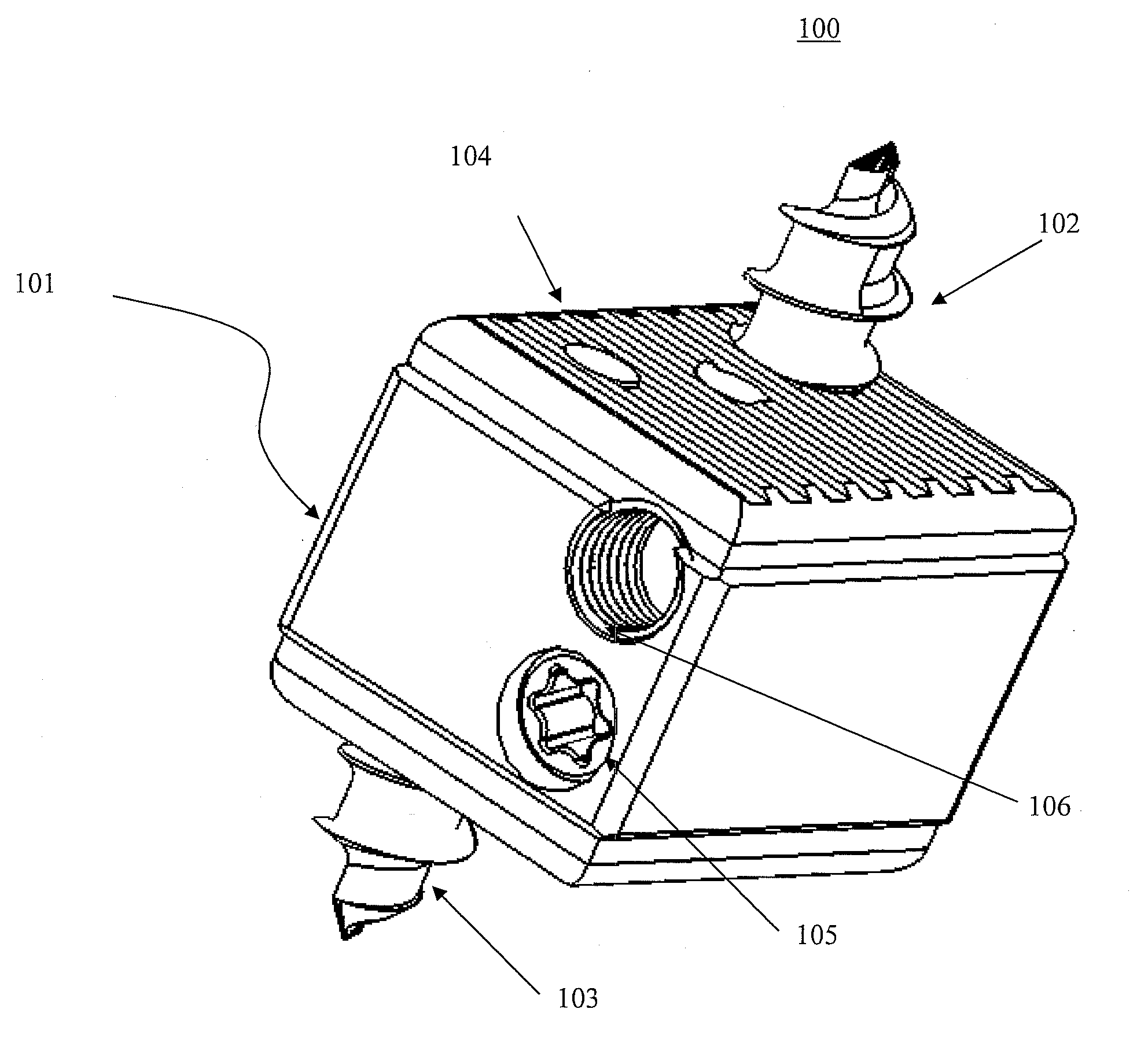
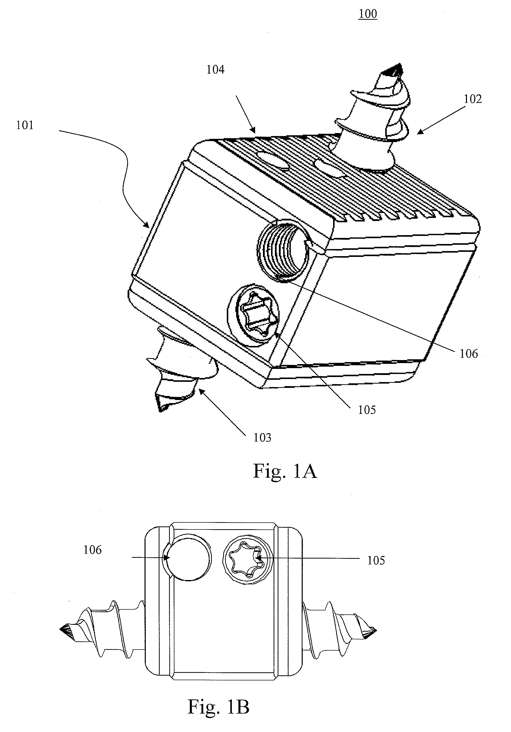
[0038] Referring to FIGS. 1A-5C the above described problem can be solved in the cervical, thoracic and lumbar spine by insertion into the denuded intervertebral disc space a bidirectional fixating transvertebral (BDFT) screw or (UBS) screws 100.

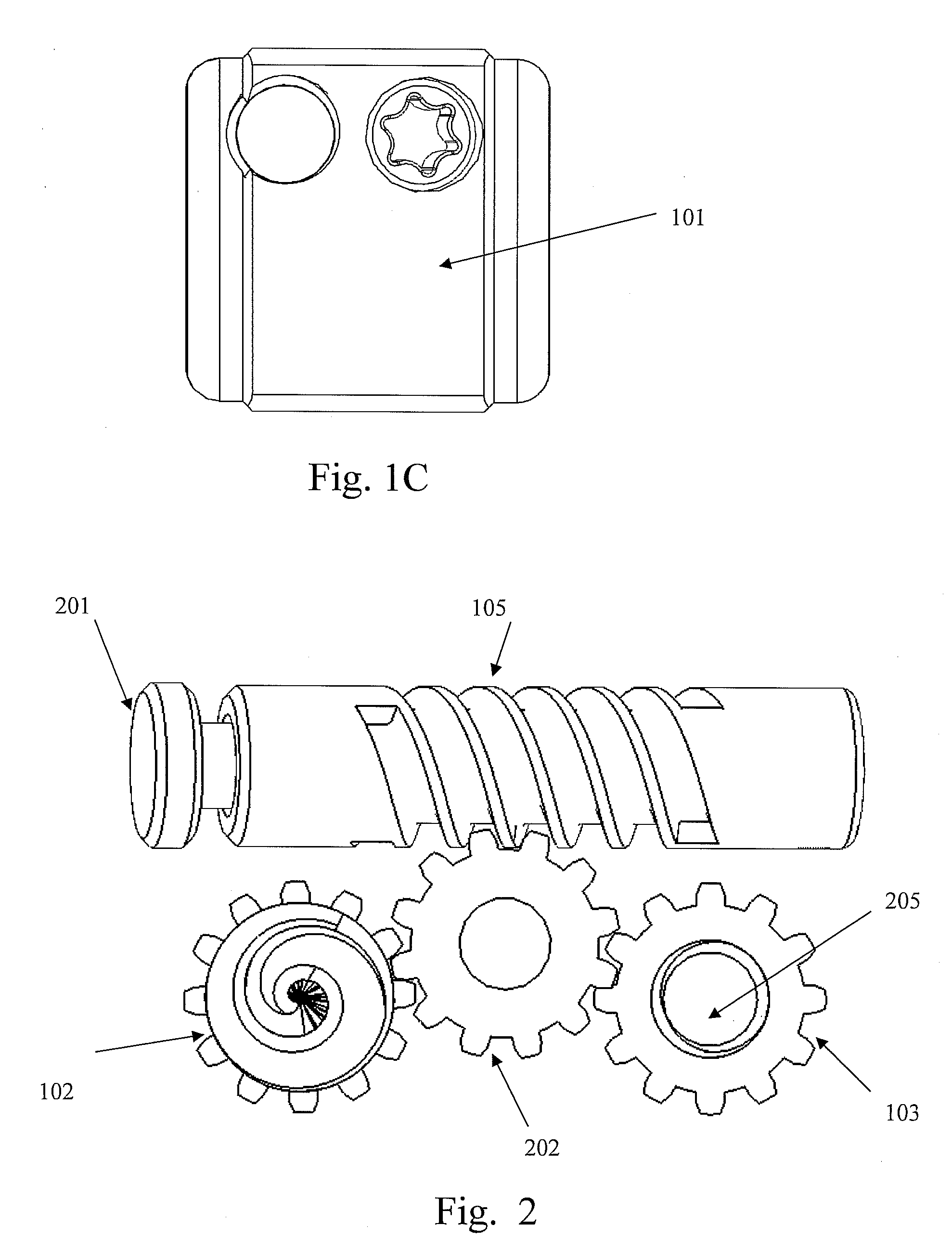
[0039]FIGS. 1A through 1C illustrate three-dimensional views of the UBS / BDFT screw 100. All its inner components are in the gear box casing 101. The internal mechanisms are illustrated in FIGS. 2-5C. FIG. 1A illustrates the isometric view of the UBS 100 showing the outer gear box 101 containing the external mechanism, with superior screw 102 and inferior screw 103 extended. There are serrations 104 on the superior and inferior surfaces of the box 101 intended to integrate with the surface of the superior and inferior vertebral body surfaces. The gear box 101 which is made either of PEEK (polyethylene-ketol) or titanium acts as a column preventing subsidence of the disc space. Also seen are the surface of the worm driv...


PUM


Abstract

An apparatus and method for joining members together using a self-drilling screw apparatus or stapling apparatus are disclosed. The screw apparatus includes a worm drive screw, a spur gear and superior and inferior screws which turn simultaneously in a bi-directional manner. A rotating mechanism drives the first and second screw members in opposite directions and causes the screw members to embed themselves in the members to be joined. The screw apparatus can be used to join members such as bones, portions of the spinal column, vertebral bodies, wood, building materials, metals, masonry, or plastics. A device employing two screws (two-in-one) can be combined with a capping horizontal mini-plate. A device employing three screws can be combined in enclosures (three-in-one). The stapling apparatus includes grip handles, transmission linkages, a drive rod a fulcrum and a cylinder. The staple has superior and inferior segments with serrated interfaces, a teethed unidirectional locking mechanism and four facet piercing elements. The staples can be also be used to join members such as bones, portions of the spinal column, or vertebral bodies.

Description

[0001] This application is a Continuation-In-Part Application of copending application Ser. No. 11 / 208,644, filed on Aug. 23, 2005 for which priority is claimed under 35, U.S.C. §120; and this application also claims priority under 35 U.S.C. §119(e) of U.S. provisional application No. 60 / 670,231, filed on Apr. 12, 2005; the entire contents of all the above identified patent applications are hereby incorporated by reference.FIELD OF INVENTION [0002] The present invention relates to a unique universal bidirectional screw (UBS) system, and in particular its application to the spine, also referred to as bi-directional fixating transvertebral (BDFT) screws which can be used to supplement other intervertebral spacers and / or bone fusion materials. BDFT screws can be incorporated into anterior and / or posterior cervical, thoracic and lumbosacral, novel, zero-profile, horizontal intervertebral mini-plates, and anterior cervical, thoracic and lumbosacral total interbody fusion devices (IBFD). ...

Claims


Application Information

Patent Timeline
Patent Type & Authority Applications(United States)
IPC IPC(8): A61B17/58
CPCA61B17/0642A61F2310/00029A61B17/70A61B17/7064A61B2017/0648A61F2/4405A61F2/442A61F2/4455A61F2/4611A61F2002/30507A61F2002/30517A61F2002/30525A61F2002/30579A61F2002/30828A61F2002/30841A61F2002/30904A61F2002/448A61F2002/4627A61F2002/4628A61F2220/0025A61F2310/00023A61B17/068
Inventor MOSKOWITZ, NATHANMOSKOWITZ, MOSHEHGLOZMAN, DANIEL
Owner MOSKOWITZ FAMILY LLC
Why Eureka
Try Eureka