Orthopaedic implant kit, orthopaedic surgery kit and associated method

a technology for orthopaedic surgery and implant kits, applied in the field of orthopaedics, can solve the problems of inability to fix the stem, difficult to achieve the effect of avoiding the need to disturb the fixation of the stem, and reducing the risk of fractur

Active Publication Date: 2007-03-01
DEPUY PROD INC
View PDF67 Cites 18 Cited by
  • Summary
  • Abstract
  • Description
  • Claims
  • Application Information

AI Technical Summary

Benefits of technology

[0027] An aspect of the present invention is in the form of a hip stem that utilizes a modular neck portion. The hip stem includes two main parts. These parts are a hip stem body and a modular neck portion. The modular neck provides the surgeon the ability to adjust the proximal-distal head height and the head offset. These adjustments may be either independent or in combination with each other. The adjustment can be made after the stem is seated and fixed into place, eliminating the need to disturb the fixation of the stem. The adjustment can take place as fine tuning at the end of the initial orthopaedic surgery or upon a revision surgery when it is determined that the cause for the revision (such as instability or leg length discrepancy) may be addressed by adjustment.

Problems solved by technology

Currently in total hip arthroplasty, a major critical concern is the instability of the joint.
Dislocation is particularly a problem in total hip arthroplasty.
The combination of all these biomechanic options is rather complex.
Improper version can lead to dislocation and patient dissatisfaction.
However, it is a more challenging issue with the advent of stems with additional modularity.
Therefore, anteversion is limited.
These monolithic stems have limited flexibility for rotational alignment since the distal stem must follow the bow of the patient's femur and this may not provide an operable biomechanical result.
Also, mono-block stems are not designed to be used in minimally invasive surgery and are not optimal for use with minimally invasive surgery procedures.
Surgical variables such as leg length discrepancy may result in surgical error that may need to be corrected or optimized.
Further, due to implant subsidence during the use of an implant, the head-height at a revision surgery may need to be corrected.
Such removal of the stem from the femur may make the revision surgery quite difficult in that the stem tends to engrow with the tissues of the bone.
Also, removal of the stem may lead to significant loss of bone, which can compromise the fixation of the stem upon re-implantation.
Further mono-block stems are not easily used in minimally invasive hip procedures where the incision through the skin and soft tissue is minimized.
The surgeon may have difficulty to work in the joint space after the stem is in place.
The long stem trials do not have the transverse bolts and are thus not rotationally stable during trial reduction and therefore are not always used by the surgeon.
The use of multiple neck segments is not advantageous since it requires more time, increased instrument cost and increased space in the instrument sterilization case.
This design, however, does not mimic the exact geometry of the actual implant.
While it is desired to be able to try several neck offsets relative to the broach in order to achieve a proper head positioning for the final implant, the prior art is deficient.
Where vertical height is restricted during surgery, especially in current, less invasive arthroplasty procedures, vertical height adjustment is undesirable.
In many of these designs the neck cannot be removed or replaced to adjust head-height or offset without disturbing the fixation of at least the modular proximal body portion of the stem.

Method used


Image

  • Orthopaedic implant kit, orthopaedic surgery kit and associated method
  • Orthopaedic implant kit, orthopaedic surgery kit and associated method
  • Orthopaedic implant kit, orthopaedic surgery kit and associated method

Examples


Embodiment Construction

[0089] Embodiments of the present invention and the advantages thereof are best understood by referring to the following descriptions and drawings, wherein like numerals are used for like and corresponding parts of the drawings.

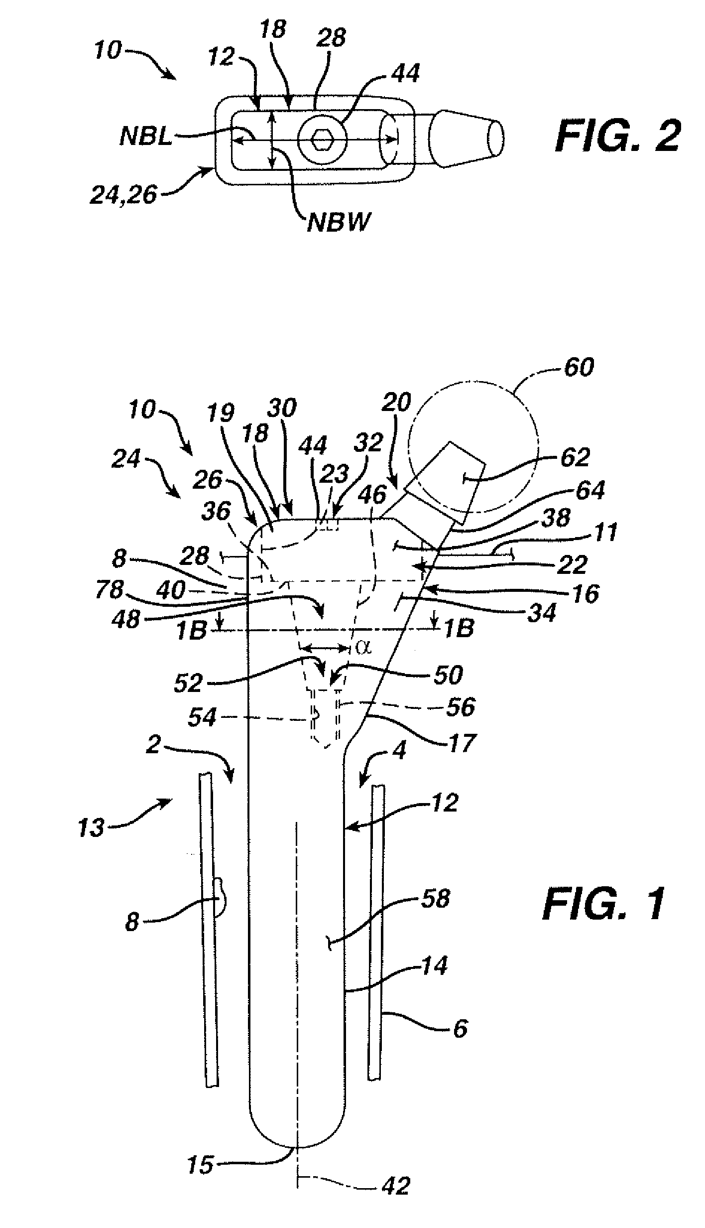
[0090] According to the present invention and referring now to FIG. 1, an embodiment of the present invention is shown as hip stem 10. Hip stem 10 is utilized for performing hip arthroplasty. The hip stem 10 is designed to be fitted into a cavity 2 in the canal 4 of a long bone 6, for example, the femur. The hip stem 10 includes a stem component 12 including a distal stem portion 14 and a proximal body portion 16. The hip stem 10 further includes a neck component 18 which, is as shown in FIG. 1, is fixedly connectable to the stem component 12. The neck component 18 includes a proximal neck portion 20 and a distal body portion 22. The neck component 18 is adapted for removal from the femur 6 without disruption of bone 8 around the stem component 12.

[0091] To...


PUM


Abstract

A kit for use in performing revision surgery on a cavity in a canal of extending from a resected plane a long bone is provided. The kit includes a canal component fitted to the cavity. The canal component includes a canal portion having first and second ends. The canal component further includes a sleeve portion having an external periphery and an internal periphery defining an internal cavity. The kit also includes a first joint component having a body portion and a connection portion. The connection portion is fitted into the sleeve portion. A connection portion of a second joint component also may be fitted into the sleeve portion so that the external periphery of the connection portion of the first joint component is spaced inwardly from the external periphery of the sleeve portion of the canal component when the first joint component is fixedly connected to the canal.

Description

CROSS-REFERENCE TO RELATED APPLICATIONS [0001] Cross reference is made to the following applications: DEP 5419USNP titled “ORTHOPAEDIC IMPLANT, STEM AND ASSOCIATED METHOD” and DEP5557USNP titled “ORTHOPAEDIC IMPLANT STEM COMPONENT, JOINT COMPONENT, AND ASSOCIATED KIT” filed concurrently herewith which are incorporated herein by reference. TECHNICAL FIELD OF THE INVENTION [0002] The present invention relates generally to the field of orthopaedics, and more particularly, to an implant for use in arthroplasty. BACKGROUND OF THE INVENTION [0003] Patients who suffer from the pain and immobility caused by osteoarthritis and rheumatoid arthritis have an option of joint replacement surgery. Joint replacement surgery is quite common and enables many individuals to function properly when it would not be otherwise possible to do so. Artificial joints are usually comprised of metal, ceramic and / or plastic components that are fixed to existing bone. [0004] Such joint replacement surgery is other...

Claims


Application Information

Patent Timeline
Patent Type & Authority Applications(United States)
IPC IPC(8): A61F2/30A61F2/36A61F2/32A61F2/40
CPCA61F2/30767A61F2/32A61F2/34A61F2/36A61F2/3609A61F2/3662A61F2/367A61F2/3676A61F2/38A61F2/3859A61F2/389A61F2/40A61F2/4014A61F2/4059A61F2/4081A61F2/4684A61F2002/30112A61F2002/30153A61F2002/30332A61F2002/30341A61F2002/30344A61F2002/30359A61F2002/30377A61F2002/3038A61F2002/30382A61F2002/30405A61F2002/30426A61F2002/30433A61F2002/30434A61F2002/30492A61F2002/30538A61F2002/30604A61F2002/30606A61F2002/30614A61F2002/30616A61F2002/3069A61F2002/30708A61F2002/30794A61F2002/30797A61F2002/30878A61F2002/30894A61F2002/3446A61F2002/3611A61F2002/3625A61F2002/365A61F2002/3652A61F2002/3656A61F2002/3658A61F2002/4018A61F2002/4029A61F2002/4037A61F2002/4044A61F2002/4062A61F2002/4077A61F2002/4631A61F2002/4641A61F2220/0025A61F2220/0033A61F2220/0041A61F2230/0004A61F2230/0019A61F2250/0006A61F2250/0064A61F2250/0084A61F2310/00011A61F2310/00017A61F2310/00023A61F2310/00029A61F2310/00179A61F2002/30339A61F2002/30367A61F2002/30331A61F2002/3079A61F2002/3054
Inventor DIETZ, TERRY L.WAGLEY, JOHN S.
Owner DEPUY PROD INC
Why Eureka
Try Eureka