Method for operating an internal combustion engine

a technology of internal combustion engine and combustion chamber, which is applied in the direction of machines/engines, electric control, instruments, etc., can solve the problems of short ignition delay in all cylinders, and achieve the effects of low accuracy, cost-effective and simple installation, and greater tolerances and dri

Active Publication Date: 2007-03-01
ROBERT BOSCH GMBH
View PDF4 Cites 8 Cited by
  • Summary
  • Abstract
  • Description
  • Claims
  • Application Information

AI Technical Summary

Benefits of technology

[0004] In connection with the present invention, it is recognized that certain “second” sensors such as structure-borne noise sensors have a lower accuracy, and are subject to greater tolerances and more drift (due to their underlying principle) than pressure sensors, while they are relatively cost-effective and simple to install. When the method according to the present invention is used, a drift of such a (second) sensor may be not only reliably recognized, but also quantified and subsequently compensated for. The performance quantities that are important for the control and regulation of the engine, such as the start of combustion, the center of gravity of the combustion, the gas torque, the maximum pressure, the indicated work, etc., may be determined using the second sensor with a similarly high accuracy as there may be by using the first (pressure) sensor, and this is largely independent of the operating time or the age of the sensors. This allows reliable and precise operation of the engine despite the use of the relatively economical second sensor.

Problems solved by technology

Another operating state in which such a drift recognition is possible is the “conventional” operation of a diesel engine in which only a slight exhaust gas recirculation takes place, which results in a short ignition delay in all cylinders.

Method used


Image

  • Method for operating an internal combustion engine
  • Method for operating an internal combustion engine
  • Method for operating an internal combustion engine

Examples


Embodiment Construction

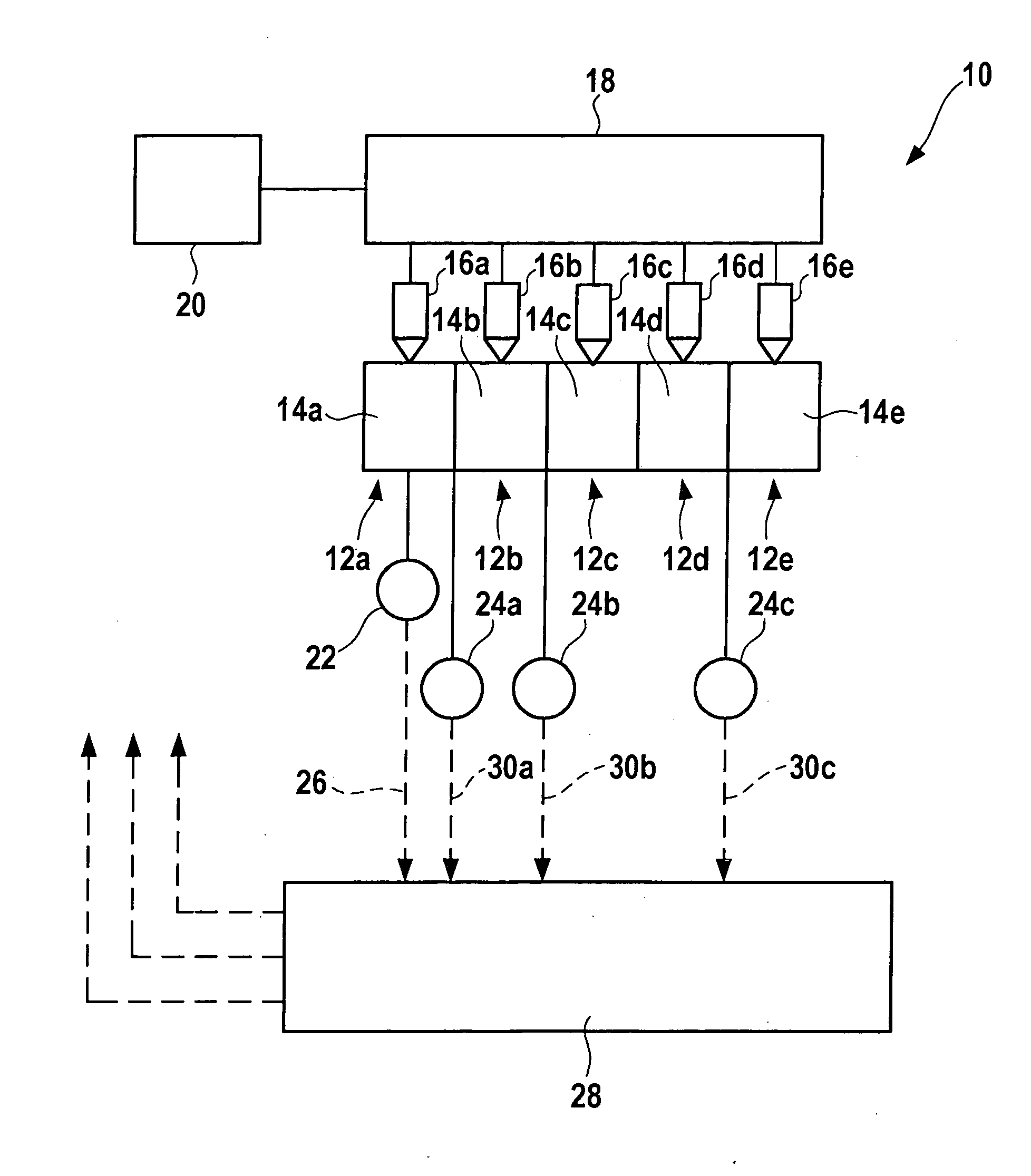
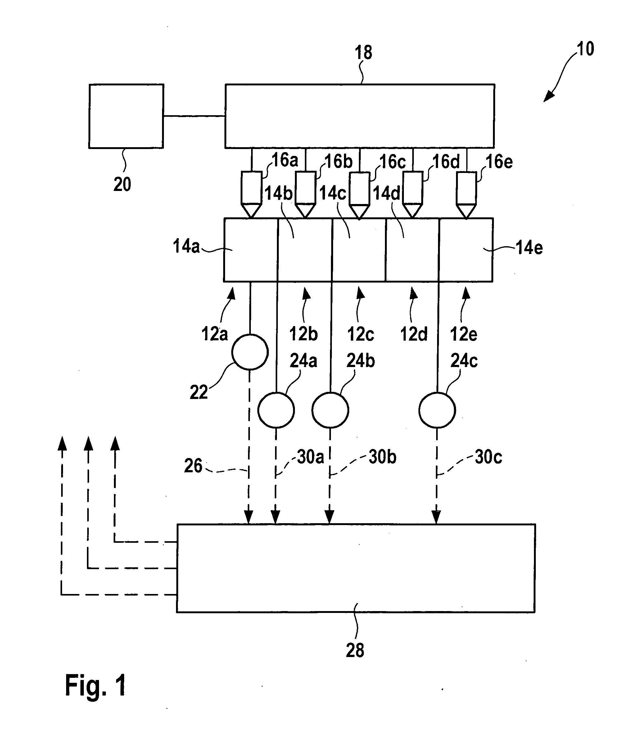
[0020] An internal combustion engine, which is generally identified by numeral 10 in FIG. 1, includes a total of five cylinders 12a, 12b, 12c, 12d, and 12e, which have the respective combustion chambers 14a, 14b, 14c, 14d, and 14e. Fuel is directly injected into combustion chambers 14a-14e via respective injectors 16a-16e, which are connected to a shared fuel high-pressure accumulator (rail) 18, which in turn is supplied with fuel by a high-pressure pumping system 20.

[0021] The pressure in combustion chamber 14a of cylinder 12a designated as guide cylinder is detected directly by a first sensor, namely a pressure sensor 22. A second sensor, designed as a structure-borne noise sensor 24a, is situated between cylinders 12a and 12b. There is a further sensor, designed as a structure-borne noise sensor 24b, between cylinders 14b and 14c, and a third structure-borne noise sensor 24c is situated between cylinders 12d and 12e. Pressure sensor 22 delivers a pressure signal 26 to a control ...


PUM


Abstract

In a method for operating an internal combustion engine, a first data quantity is derived based on a signal of a first sensor which detects the pressure in a first combustion chamber of a plurality of combustion chambers, and a second data quantity is derived based on a signal of a second sensor, which second data quantity is a function of the pressure variation in at least one of the plurality of combustion chambers. The first data quantity and the second data quantity are functions of the pressure variation in the same combustion chamber, and a drift of the second sensor is ascertained from a change over time in the second data quantity with respect to the first data quantity.

Description

FIELD OF THE INVENTION [0001] The present invention relates to a method for operating an internal combustion engine, as well as to a computer program and a control device for implementing the method. BACKGROUND INFORMATION [0002] In a method for operating an internal combustion engine described in published German patent document DE 102 27 279, a pressure sensor which detects the pressure in a cylinder (guide cylinder) of the engine is associated with this cylinder. Furthermore, the engine has a structure-borne noise sensor, which indirectly detects the pressure changes in the individual cylinders. The pressure variation plays an important role in combustion control according to this known method: the agreement of the detected combustion chamber pressure with the combustion chamber pressure obtained from the signal of the structure-borne noise sensor is verified for the guide cylinder. If, during a certain period of time, the ascertained pressures differ by more than a certain value...

Claims


Application Information

Patent Timeline
Patent Type & Authority Applications(United States)
IPC IPC(8): G06F19/00F02M7/00
CPCF02D35/021F02D35/023F02D35/028F02D35/024F02D2200/025F02D41/2451F02D41/2474F02D41/0085
Inventor BIRK, MANFREDDAMITZ, JENSMOESSINGER, JUERGENKESSLER, MICHAELDAUTEL, VINCENTKOSITZA, NICOLE
Owner ROBERT BOSCH GMBH
Why Eureka
Try Eureka