Container handling system

a container and handling system technology, applied in the field of container handling system, can solve the problems of water spillage after the container, hot-filled solid products are not easily removed, and containers with panels and protruding ribs detract from the desired smooth, sleek look of glass containers, and achieve the effect of smooth label placemen

Active Publication Date: 2007-03-08
CO2 PAC
View PDF98 Cites 136 Cited by
  • Summary
  • Abstract
  • Description
  • Claims
  • Application Information

AI Technical Summary

Benefits of technology

[0007] A three stage system utilizes a simplified, blow-molded container that retains its structural integrity after being hot filled and cooled through conventional food or beverage systems. That is, a simplified container according to the invention is a container with at least a portion of the container side walls being relatively smooth that can be filled with a hot product, such as a liquid or a partly solid product, and retain the requisite strength so that a number of containers can be stacked on top of one another with the resultant stack being sturdy. The relatively smooth surface is relatively or completely free of structural geometry, such as the structural ribs, riblets, or vacuum panels. In addition, the simplified, blow-molded container still retains the features of vacuum packaging and the ability to accommodate internal changes in pressure and volume as a result of heating and cooling. That is, the simplified container may employ a single main invertible projection by itself to take up the vacuum; or, the simplified container may have a few main projections that take up the vacuum while still providing a substantial portion of the container to be relatively smooth for label placement, for example. Alternatively, depending upon the size of the container, a mini vacuum panel to supplement the main invertible projection may be used to complete the removal of the resultant vacuum and finish the look of the cooled container. Unlike conventional containers, structural ribs between vacuum panels are not necessary in a simplified container where a substantial portion of the container body is relatively smooth.
[0008] Initially, a container is blow-molded with an approximately polygonal, circular or oval projection extending, for example, from a base of the container. The approximately polygonal, circular or oval projection may project from the shoulders of the container, or from another area of the container. If the projection extends from the base of the container, before the container exits the blow-molding operation, the projection may be inverted inside the container so that the base surface of the blow-molded container is relatively flat so that the container can be easily conveyed on a table top, without toppling.
[0009] In the next stage, the blow-molded container may be picked-up by a robotic arm or the like and placed into a production line conveyor where it is supported by its neck. A mechanical operation causes a rod to be inserted in the neck of the container and pushes the inverted projection outside the container to provide for the increased volume necessary to receive a hot-filled product, as well as accommodating variations in pressure due to temperature changes during cooling. Alternatively, compressed air or other pressure may be used to push the inverted projection outside of the container. With the projection extending outside the container, the container is filled with a hot product, capped and moved to the cooling operation. Since the container is supported by its neck during the filling and capping operations, the process according to the invention provides maximum control of the containers while being filled and capped.
[0014] A system for manufacturing a simplified plastic container that is to be filled with a hot product, comprising the steps of blow-molding parison to form a container body, the container body having a neck, a base, a smooth side surface surrounding an interior of the container body and a projection extending from the container; filling the container body with the hot product in a production line; capping the neck of the filled container body with a cap in the next operation of the production line; cooling the container body filled with the hot product; and pushing the projection extending from the cooled container body into the interior of the container body so that the resultant, filled and cooled container body is relatively flat. If the projection extends from a base of the container, this inversion permits conveying of the container body on its base.

Problems solved by technology

While the protruding rib structures improve the strength of the container that is blow-molded out of plastic, the resultant, lightweight, blow-molded containers with panels and protruding rib structure detract from the desired smooth, sleek look of a glass container.
Thus, hot-filled containers are provided with more recesses and corners from which hot-filled solid products are not easily removed.
Or, if the hot-filled product is subsequently chilled by placing the container in ice, the label covering the panels with protruding structures traps water inside the recessed panels resulting in spillage of the water after the container is removed from ice.

Method used


Image

  • Container handling system
  • Container handling system
  • Container handling system

Examples


Embodiment Construction

[0032] Embodiments of the invention are discussed in detail below. In describing embodiments, specific terminology is employed for the sake of clarity. However, the invention is not intended to be limited to the specific terminology so selected. While specific exemplary embodiments are discussed, it should be understood that this is done for illustration purposes only. A person skilled in the relevant art will recognize that other components and configurations can be used without parting from the spirit and scope of the invention. All references cited herein are incorporated by reference as if each had been individually incorporated.

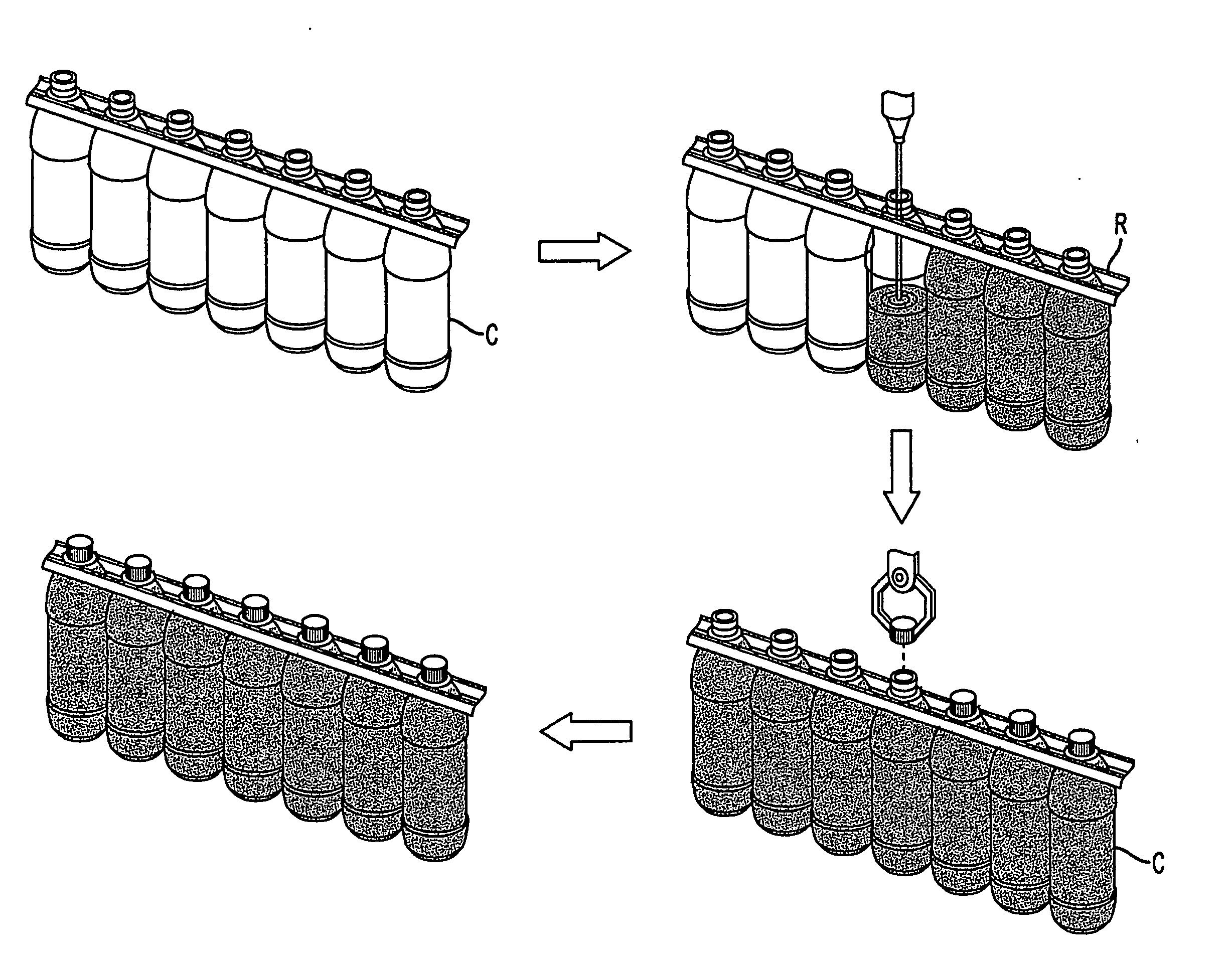
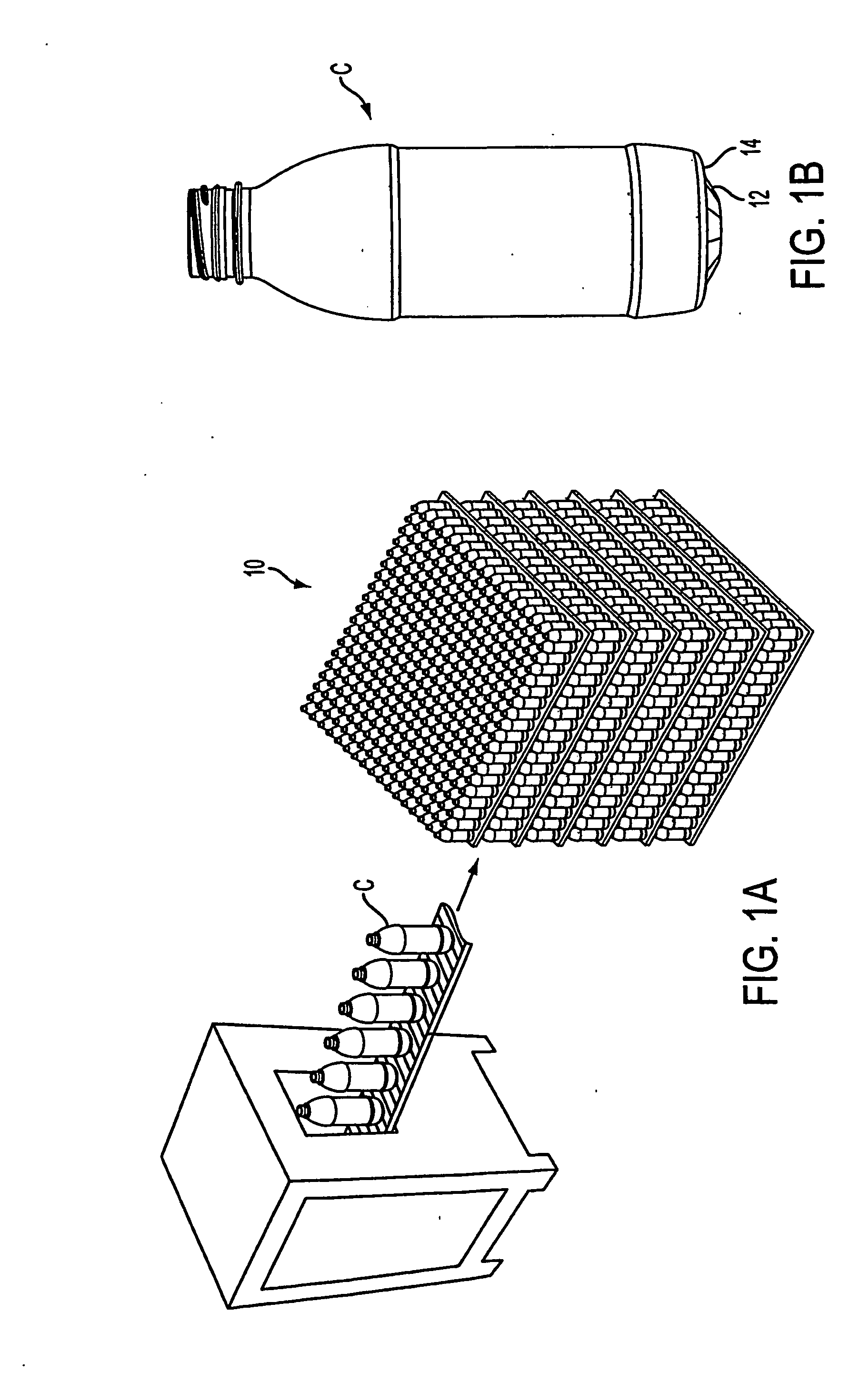
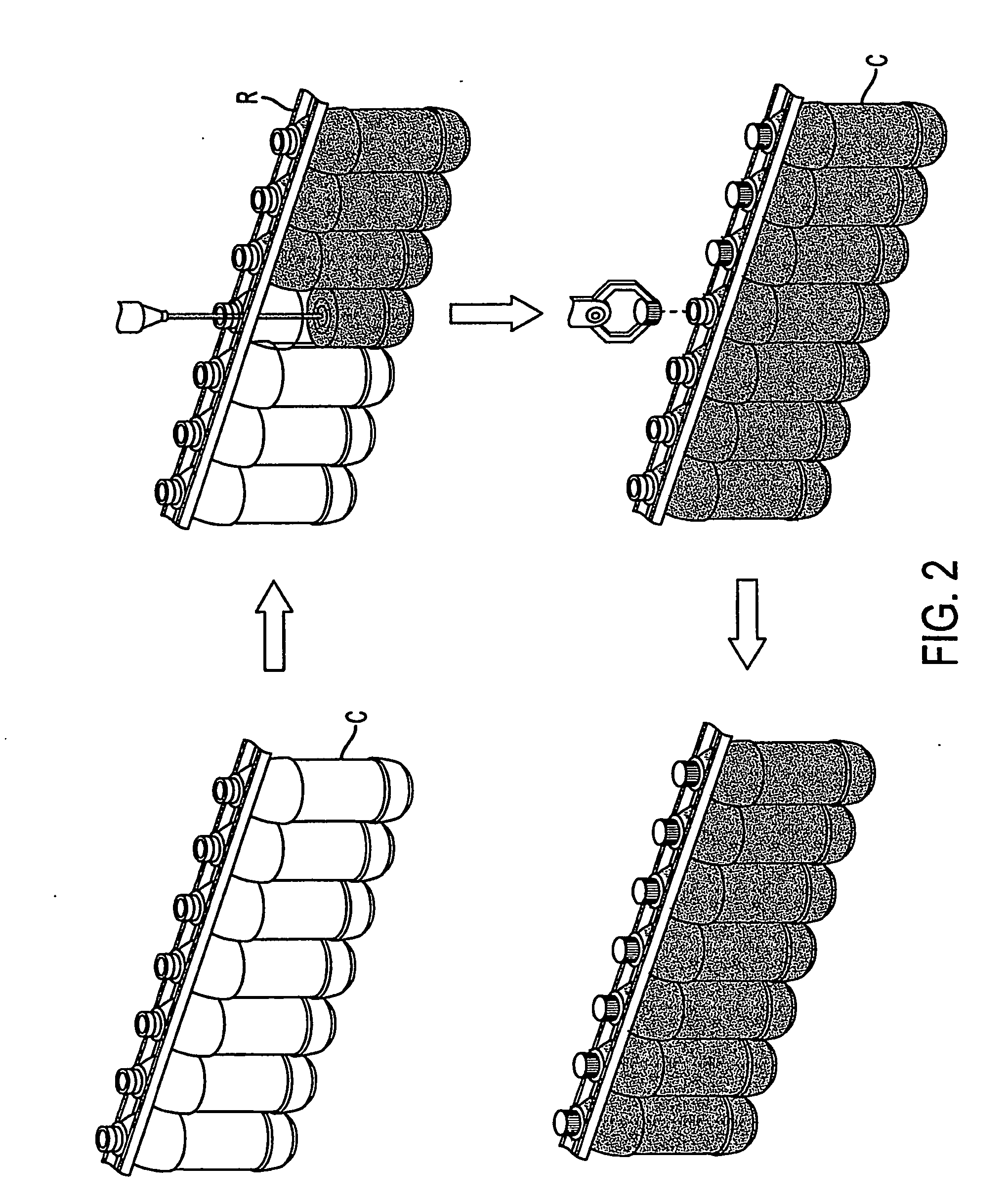
[0033] As shown schematically in FIG. 1A, containers C formed in a blow-molding or forming operation may exit the blow-molding operation with a base designed so that the container can stand on its own. That is, a container with a relatively smooth side surrounding its interior may be blow-molded with a projection extending from the base of the smooth si...


PUM

PropertyMeasurementUnit
forceaaaaaaaaaa
vacuumaaaaaaaaaa
volumeaaaaaaaaaa

Abstract

A system for processing a simplified plastic container (C) that is to be filled with a hot product includes the step of blow-molding parison to form a container body, where the container body has a neck, a base, a side surface relatively free of structural geometry that surrounds an interior of the container body and, prior to being filled with the hot product, a projection (12) extending from the container body. After the container body is filled with a hot product in a production line, the neck of the filled container body is capped with a cap and then, the container body is cooled. During the cooling operation, the hot product is contracted so that the projection extending from the container can be pushed (P) into the container body like a traditional push-up so that the resultant, filled and cooled container body is relatively free of structural geometry.

Description

BACKGROUND OF THE INVENTION [0001] 1. Field of the Invention [0002] The present invention relates generally to a container handling system and a process for filling, capping and cooling hot-filled containers with a projection, and more particularly to a system and process for filling, capping and cooling hot-filled, blow-molded containers with a projection that can extend outside the container during the filling process and be inverted inside the container before the filled container is removed from a production line. [0003] 2. Related Art [0004] Known blow-molded containers are usually made of plastic and employ flex panels that reinforce the integrity of the container while accommodating internal changes in pressures and volume in the container as a result of heating and cooling. This is especially true with hot-fillable containers, or containers in which hot products are injected during a filling process, capped and cooled to room temperature thereby allowing the filled product t...

Claims


Application Information

Patent Timeline
Patent Type & Authority Applications(United States)
IPC IPC(8): B65B63/08B67B3/28B65BB65B21/12B65D1/02B65D79/00B67C3/14
CPCB65B21/12B65B61/24B65B63/08B67C3/045B67C3/14B65B9/042B67C7/00B67C7/0026B67C7/0053B67C2003/226B67C3/242B65D1/0246B65D1/0261B65D1/40
Inventor KELLEY, PAULGOSS, KENTSHEETS, PHILIPLYON, TEDRYL-KUCHAR, CHARLES A.
Owner CO2 PAC
Why Eureka
Try Eureka