
Controller of internal combustion engine

a controller and internal combustion engine technology, applied in electrical control, force/torque/work measurement apparatus, instruments, etc., can solve problems such as deviation in air-fuel ratio, deterioration of startability or exhaust emission, and corrective fuel correction, so as to improve the startability of the engine, the effect of accurate control and smooth starting

Active Publication Date: 2007-03-08
DENSO CORP
View PDF11 Cites 12 Cited by
  • Summary
  • Abstract
  • Description
  • Claims
  • Application Information

AI Technical Summary

Benefits of technology

The present invention provides a controller for an internal combustion engine that can accurately control the generated torque to the target air-fuel ratio in an early stage of a start-up of the engine and smoothly starting with an appropriate rotation speed behavior. The controller uses an interval setting device to calculate the rotation speed of the engine based on the angular speed of the crankshaft or information correlated with the angular speed in a rotation speed calculation interval set across the top dead center of the combustion stroke. The generated torque is accurately controlled to the appropriate torque by calculating the rotation speed increase or torque fluctuation of the engine during the rotation speed increasing period after the beginning of the start-up of the engine and correcting the torque to conform to the target air-fuel ratio. The invention improves the startability of the engine and ensures a smooth start-up with an appropriate rotation speed behavior.

Problems solved by technology

This can deteriorate startability or exhaust emission.
However, the control system of JP-A-H08-284708 cannot perform appropriate fuel correction corresponding to the fuel property before the learning of the fuel property sufficiently advances after the start-up of the engine.
Accordingly, there is a possibility that a deviation in the air-fuel ratio is generated due to the fuel property and the rotation speed fluctuation is caused.
Therefore, there is a possibility that the rotation speed fluctuation is caused before the start-up that is not optimum is sensed.
Therefore, even if the generated torque is deviated from the appropriate torque corresponding to the target air-fuel ratio, the deviation of the torque cannot be corrected.
As a result, the engine cannot be started smoothly with an appropriate rotation speed behavior.

Method used


Image

  • Controller of internal combustion engine
  • Controller of internal combustion engine
  • Controller of internal combustion engine

Examples


Embodiment Construction

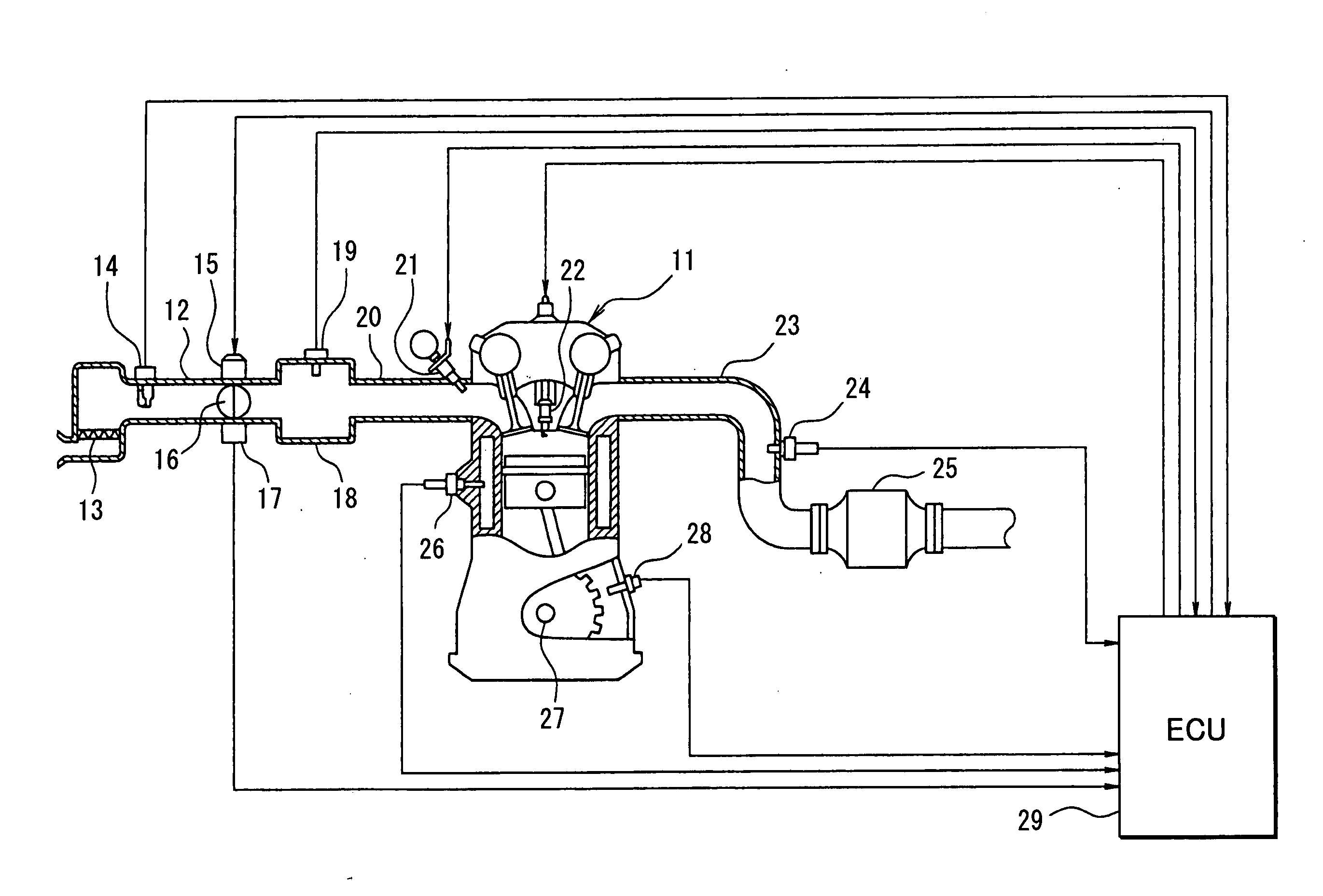
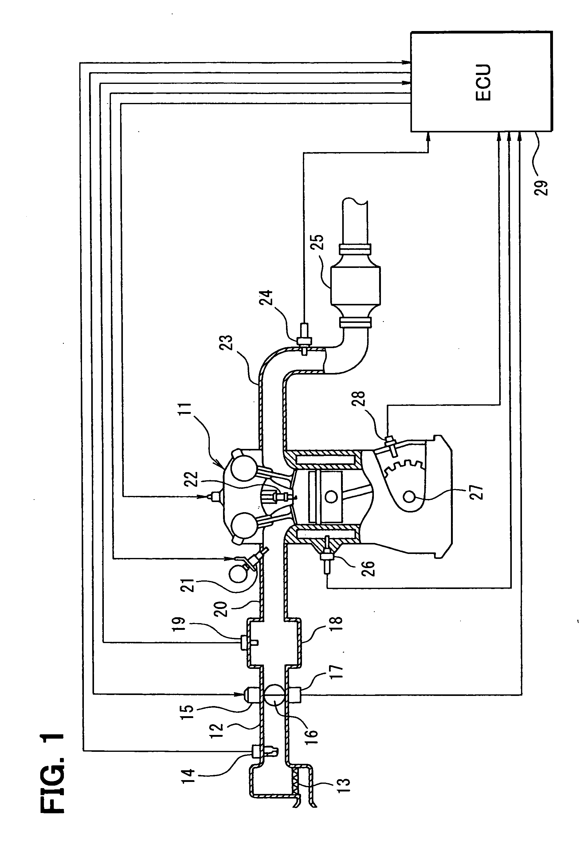
[0034] Referring to FIG. 1, an engine control system according to a first example embodiment of the present invention is illustrated. An air cleaner 13 is provided at the upstream-most portion of an intake pipe 12 of an internal combustion engine 11. An airflow meter 14 for sensing an air intake amount is provided downstream of the air cleaner 13. A throttle valve 16, an opening degree (throttle opening degree) of which is regulated by a motor 15, and a throttle opening degree sensor 17 for sensing the opening degree of the throttle valve 16 are provided downstream of the airflow meter 14.

[0035] A surge tank 18 is provided downstream of the throttle valve 16. An intake pipe pressure sensor 19 for sensing intake pipe pressure is provided in the surge tank 18. The surge tank 18 is provided with an intake manifold 20 for introducing the air into respective cylinders of the engine 11. Fuel injection valves 21 for injecting the fuel are attached near intake ports of the intake manifold ...


PUM


Abstract

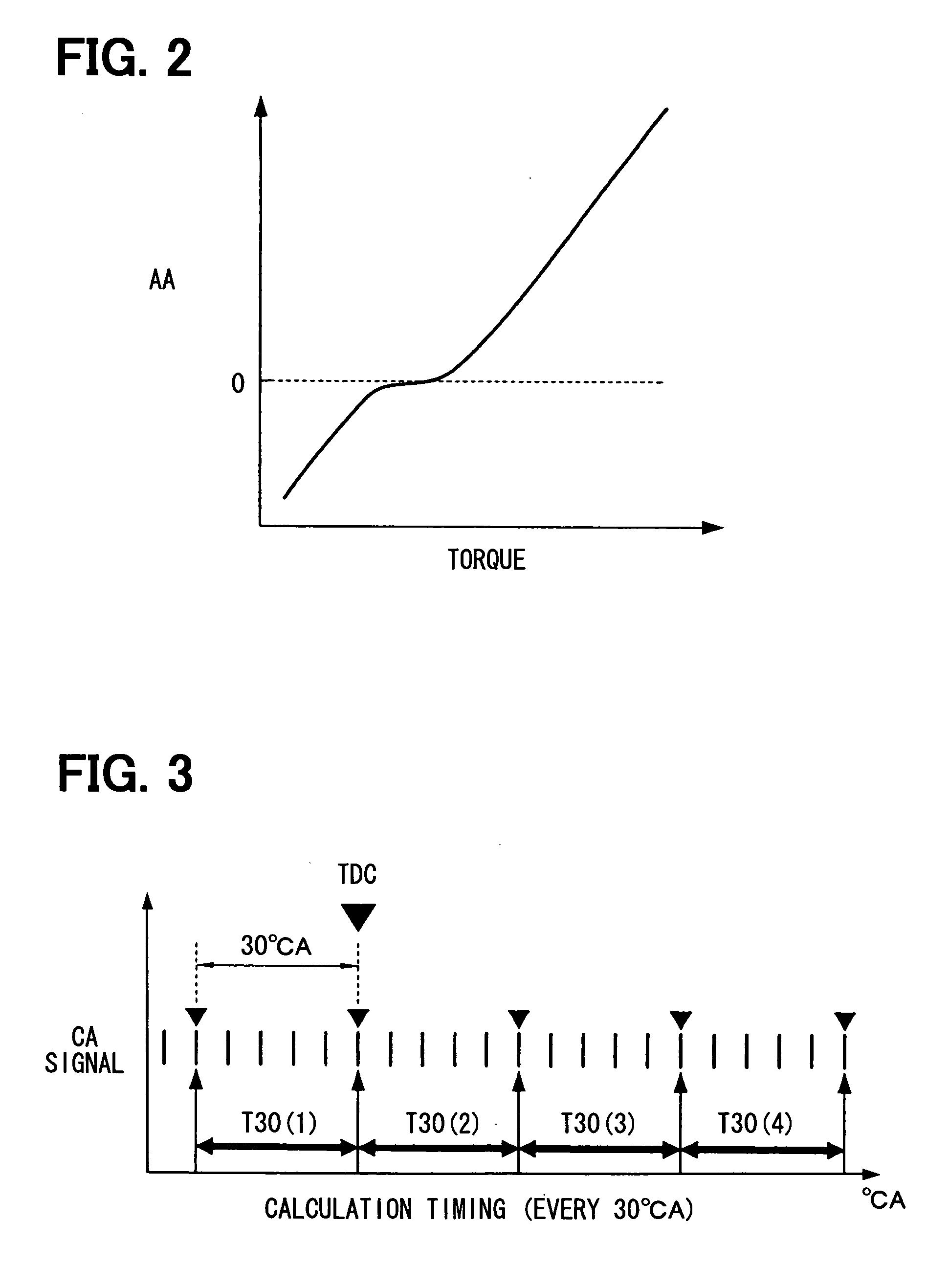
A rotation speed calculation interval is set near a combustion top dead center of each cylinder of an engine. An interval rotation time necessary for a crankshaft to rotate through the rotation speed calculation interval is calculated as angular speed information of the crankshaft in the rotation speed calculation interval for each combustion stroke of the engine. Engine rotation speed is calculated based on the interval rotation time. The angular speed information of the crankshaft in the rotation speed calculation interval set near the combustion top dead center reflects a combustion state or generated torque. By calculating the engine rotation speed based on the angular speed information, the engine rotation speed highly correlated with the combustion state or the generated torque of the engine can be calculated.

Description

CROSS REFERENCE TO RELATED APPLICATION [0001] This application is based on and incorporates herein by reference Japanese Patent Application No. 2005-258695 filed on Sep. 7, 2005 and Japanese Patent Application No. 2005-267746 filed on Sep. 15, 2005. BACKGROUND OF THE INVENTION [0002] 1. Field of the Invention [0003] The present invention relates to a controller of an internal combustion engine for calculating rotation speed of the engine and for improving startability of the engine. [0004] 2. Description of Related Art [0005] A control system of an internal combustion engine calculates engine rotation speed in a predetermined cycle to comprehend an engine operation state. For example, a control system described in Japanese Patent No. 3490541 calculates a time difference between pulses outputted from a sensor every time a crankshaft of the engine rotates through a predetermined crank angle (CA) and calculates the engine rotation speed based on summation calculation value of a predete...

Claims


Application Information

Patent Timeline
Patent Type & Authority Applications(United States)
IPC IPC(8): G01M15/00
CPCF02D41/0097
Inventor KITA, MASAYUKI
Owner DENSO CORP
Learn More