Automotive dynamoelectric machine
a dynamoelectric machine and motor technology, applied in the direction of mechanical equipment, bearing unit rigid support, coupling device connection, etc., can solve the problems of the service life of rolling bearings and brushes, etc., and achieve the effect of extending the service life of brushes and rolling bearings
- Summary
- Abstract
- Description
- Claims
- Application Information
AI Technical Summary
Benefits of technology
Problems solved by technology
Method used
Image
Examples
embodiment 1
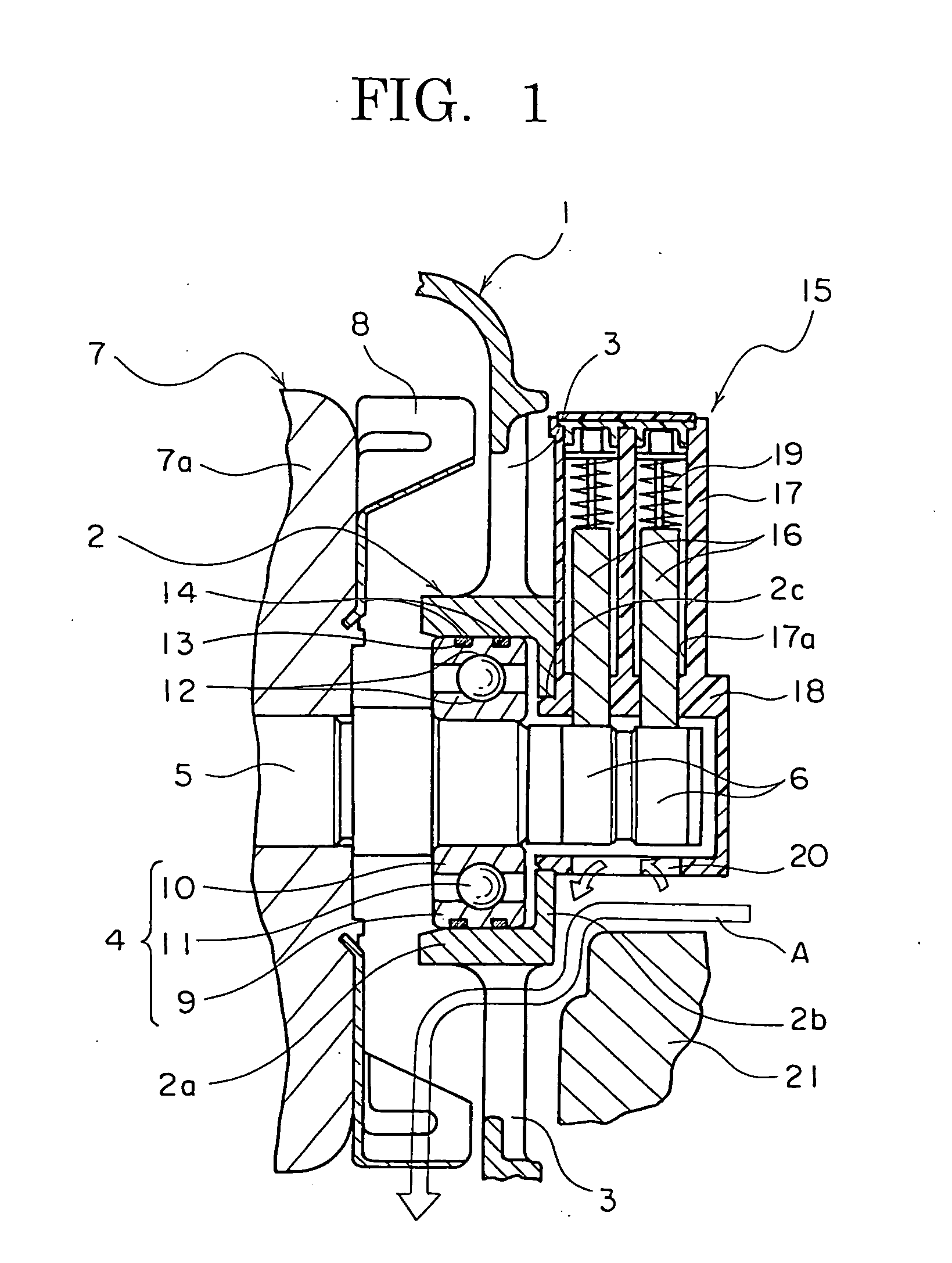
[0017]FIG. 1 is a longitudinal section of part of an automotive dynamoelectric machine according to Embodiment 1 of the present invention.
[0018] In FIG. 1, a rear bracket 1 is made of aluminum that is formed so as to have a bowl shape and a rear-end bearing accommodating portion 2 that has a floored cylindrical shape that is constituted by a cylindrical portion 2a and a floor portion 2b is formed integrally on a central portion of an end surface of the rear bracket 1 such that an open end thereof faces inward. A shaft insertion aperture 2c is disposed through a central portion of the floor portion 2b of the rear-end bearing accommodating portion 2. A plurality of air intake apertures 3 are disposed through the rear bracket 1 in a vicinity of the rear-end bearing accommodating portion 2. Although not shown, a plurality of air discharge apertures are disposed through a side surface of the rear bracket 1.
[0019] Moreover, although not shown, a front bracket that functions together wit...
embodiment 2
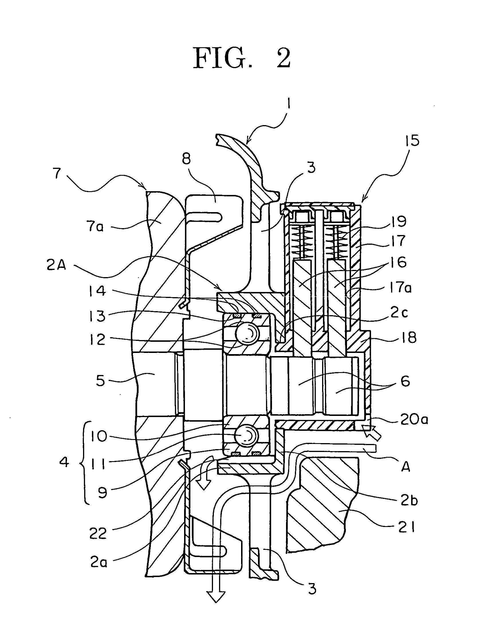
[0039]FIG. 2 is a longitudinal section of part of an automotive dynamoelectric machine according to Embodiment 2 of the present invention, FIG. 3 is a cross section that explains a configuration of a rear-end bearing accommodating portion in the automotive dynamoelectric machine according to Embodiment 2 of the present invention, and FIG. 4 is a partial cross section that shows a state in which a rolling bearing is accommodated in the rear-end bearing accommodating portion in the automotive dynamoelectric machine according to Embodiment 2 of the present invention.
[0040] In FIGS. 2 through 4, a second slit 22 that functions as a second ventilation channel is recessed into an inner wall surface of a cylindrical portion 2a of a rear-end bearing accommodating portion 2A so as to have a groove direction that is aligned in an axial direction of the shaft 5 and so as to extend from a floor portion 2b to an opening. A first slit 20a that functions as a first ventilation channel is disposed...
embodiment 3
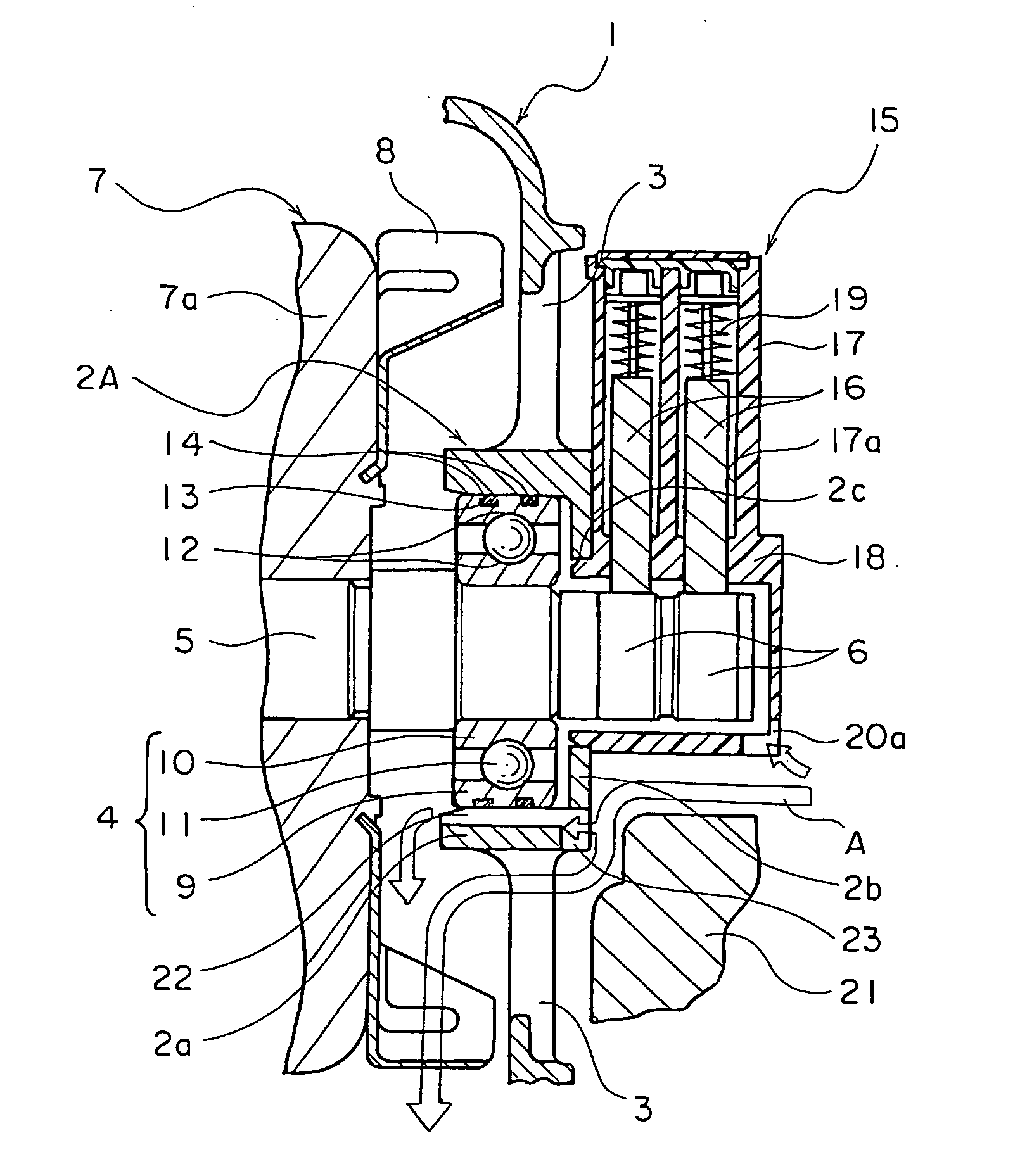
[0048]FIG. 5 is a longitudinal section of part of an automotive dynamoelectric machine according to Embodiment 3 of the present invention.
[0049] In FIG. 5, a third slit 23 that functions as a third ventilation channel is disposed through an intersecting portion between a cylindrical portion 2a and a floor portion 2b of a rear-end bearing accommodating portion 2A so as to be positioned so as to face downward when the automotive dynamoelectric machine is mounted to a vehicle. A second slit 22 and an external portion of the rear-end bearing accommodating portion 2A thereby communicate through the third slit 23.
[0050] Moreover, the rest of this embodiment is configured in a similar manner to Embodiment 2 above.
[0051] In Embodiment 3, when the centrifugal fans 8 are driven, external air passes between the slinger portion 18 and the rectifier 21 and also between the rear-end bearing accommodating portion 2A and the rectifier 21, and is sucked into the housing through the air intake ape...
PUM
 Abstract
Description
Claims
Application Information
 - R&D
- Intellectual Property
- Life Sciences
- Materials
- Tech Scout
- Unparalleled Data Quality
- Higher Quality Content
- 60% Fewer Hallucinations
Browse by: Latest US Patents, China's latest patents, Technical Efficacy Thesaurus, Application Domain, Technology Topic, Popular Technical Reports.
© 2025 PatSnap. All rights reserved.Legal|Privacy policy|Modern Slavery Act Transparency Statement|Sitemap|About US| Contact US: help@patsnap.com


