Low noise amplifier for a radio receiver

a radio receiver and amplifier technology, applied in the field of receivers, can solve the problems of difficult control of antenna impedance, power dissipation may be greater than desired, and matched impedance lna presents other problems, and achieve the effect of low nois

Inactive Publication Date: 2007-03-08
SILICON LAB INC
View PDF22 Cites 25 Cited by
  • Summary
  • Abstract
  • Description
  • Claims
  • Application Information

AI Technical Summary

Benefits of technology

[0008] In one embodiment, the present invention includes an amplifier having a transistor stage coupled between a supply voltage and a bias current. The transistor stage has an input to receive a radio frequency (RF) input signal obtained from an antenna via an RF input node. The amplifier, which may be a low noise amplifier (LNA) has an input impedance that is unmatched to a source impedance of the antenna. In some embodiments, this unmatched input impedance may be substantially greater than the source impedance, and may further be controlled based on a strength of the RF input signal. The LNA may be implemented in an integrated circuit (IC) and in some embodiments, the IC may further include a controller to adjust the bias current.

Problems solved by technology

However, by using a matched impedance, power dissipation may be greater than desired.
In addition to power dissipation issues, a matched impedance LNA presents other problems, particularly in portable applications.
Namely, it is difficult to control antenna impedance and therefore the source and amplifier may not have properly matched impedances, causing reflections.
Furthermore, a single amplifier design cannot be flexibly used in multiple designs, as it cannot be accommodated to sources having different impedances.
However, significant downsides to this approach exist.
First, the transformation network requires large components which consume board real estate and add cost.
Another concern is that the transformation network increases signal magnitude at the amplifier, which has a negative effect on intermodulation performance of the amplifier.

Method used


Image

  • Low noise amplifier for a radio receiver
  • Low noise amplifier for a radio receiver
  • Low noise amplifier for a radio receiver

Examples


Embodiment Construction

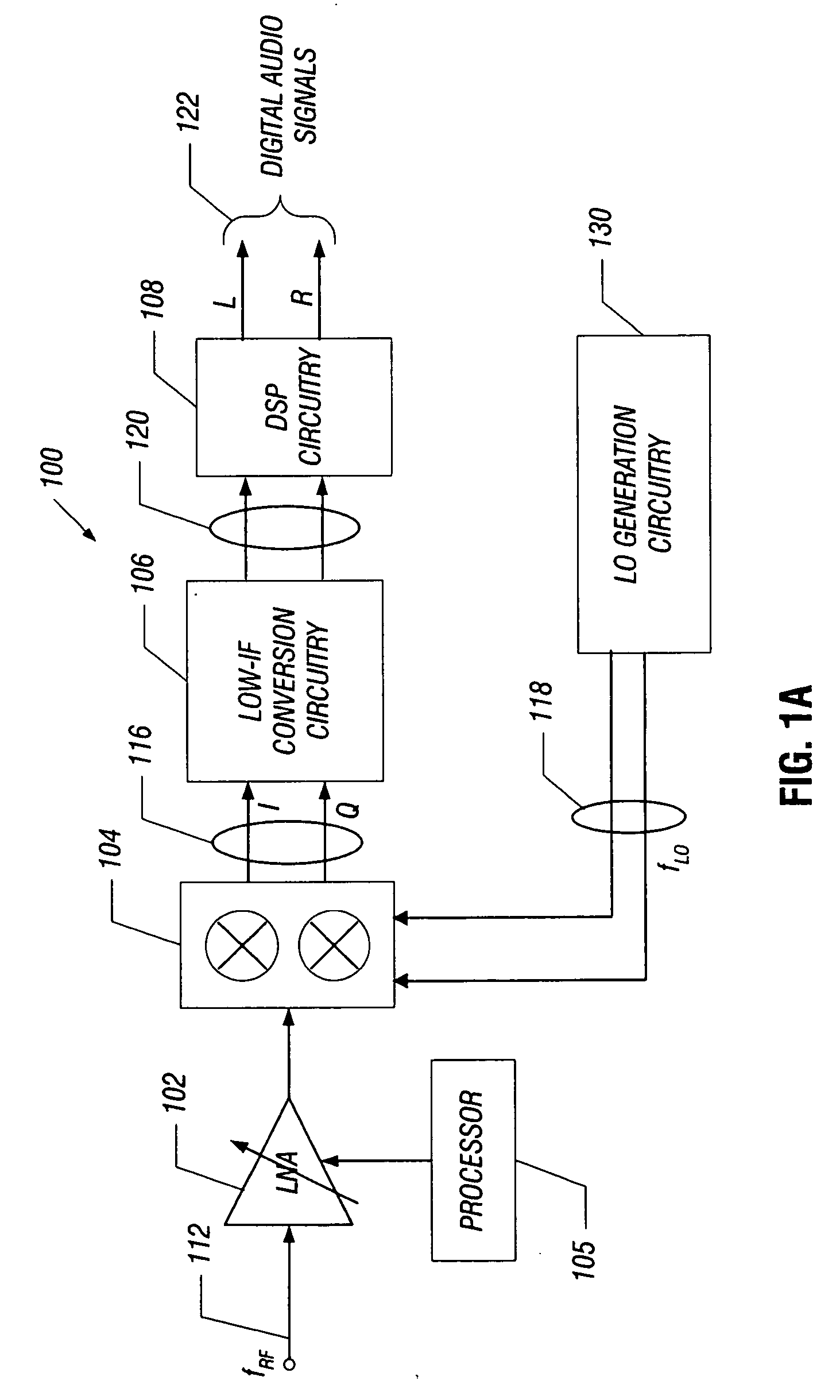
[0022]FIG. 1A is a block diagram of an embodiment 100 for an integrated terrestrial broadcast receiver that utilizes a low-IF architecture. The input signal spectrum (fRF) 112 is expected to be a radio frequency (RF) signal spectrum that includes a plurality of channels that can be tuned. It is noted that as used herein, a “radio frequency” or RF signal means an electrical signal conveying useful information and having a frequency from about 3 kilohertz (kHz) to thousands of gigahertz (GHz), regardless of the medium through which such signal is conveyed. Thus an RF signal may be transmitted through air, free space, coaxial cable, fiber optic cable, etc. More particularly, the embodiments can provide an advantageous architecture for an FM terrestrial broadcast receiver. For purposes of the description below, therefore, the RF signal spectrum (fRF) 112 will be discussed primarily with respect to the RF signal spectrum (fRF) 112 being an FM terrestrial broadcast spectrum that includes ...


PUM


Abstract

In one embodiment, the present invention includes an amplifier having a transistor stage coupled between a supply voltage and a bias current. The transistor stage has an input to receive a radio frequency (RF) input signal obtained from an antenna. The amplifier has an input impedance that is unmatched to a source impedance of the antenna. In some embodiments, this unmatched input impedance may be substantially greater than the source impedance, and may further be controlled based on a strength of the RF input signal.

Description

FIELD OF THE INVENTION [0001] The invention generally relates to a receiver that has a controllable amplifier. BACKGROUND [0002] A conventional radio frequency (RF) receiver includes various gain stages for purposes of receiving a relatively small magnitude RF signal and translating the received RF signal to an intermediate frequency (IF) signal. [0003] The RF signal that is received by the receiver typically is provided from an antenna source and varies in strength. An input stage of the receiver typically includes an amplifier such as a low noise amplifier (LNA) to amplify the incoming signal, preferably without introducing distortion. The LNA is typically designed to match the impedance of the source (e.g., antenna). In many instances, the LNA is designed to have a fixed impedance, typically 50 or 75 ohms (Ω). [0004] Conventional amplifiers for a receiver are formed using bipolar complementary metal oxide semiconductor (BiCMOS) technology. For example, a common base amplifier for...

Claims


Application Information

Patent Timeline
Patent Type & Authority Applications(United States)
IPC IPC(8): H03F3/191
CPCH03F2203/45362H03F3/45183
Inventor KASHA, DAN B.TUTTLE, G. TYSONHODGSON, GREGORY A.
Owner SILICON LAB INC
Why Eureka
Try Eureka