
Tunable filter, duplexer and communication apparatus

a technology of duplexer and filter, which is applied in the direction of electrical apparatus, coupling devices, waveguides, etc., can solve the problems of filter not being usable, diodes may be burned out, and cannot be varied steplessly

Inactive Publication Date: 2007-03-08
MURATA MFG CO LTD
View PDF5 Cites 12 Cited by
  • Summary
  • Abstract
  • Description
  • Claims
  • Application Information

AI Technical Summary

Benefits of technology

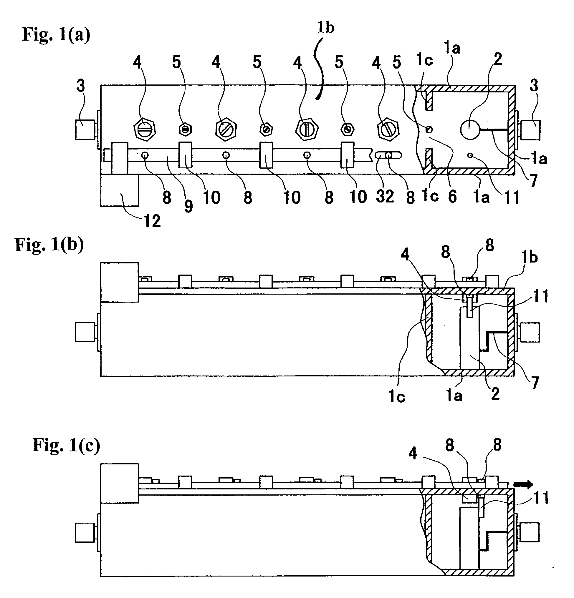
[0018] With the first or second aspect of the invention, when the position, the angle, or both, of the dielectric inserted into the resonant cavity of each semi-coaxial cavity resonator with respect to the inner conductor is varied, perturbation is applied to an electric field occurring in the resonant cavity, so that the resonant frequency of each cavity resonator may be varied. In addition, since the holders of the dielectrics are coupled by the coupling member, the frequencies of the resonators are varied immediately at the same time, and by the same variation amount. Since the displacement amount of the coupling member is arbitrarily set within a movable range, there is provided a tunable filter that allows the center frequency of the band pass filter or the center frequency of an elimination band of the band elimination filter to be arbitrarily set within the movable range, and has good responsiveness.
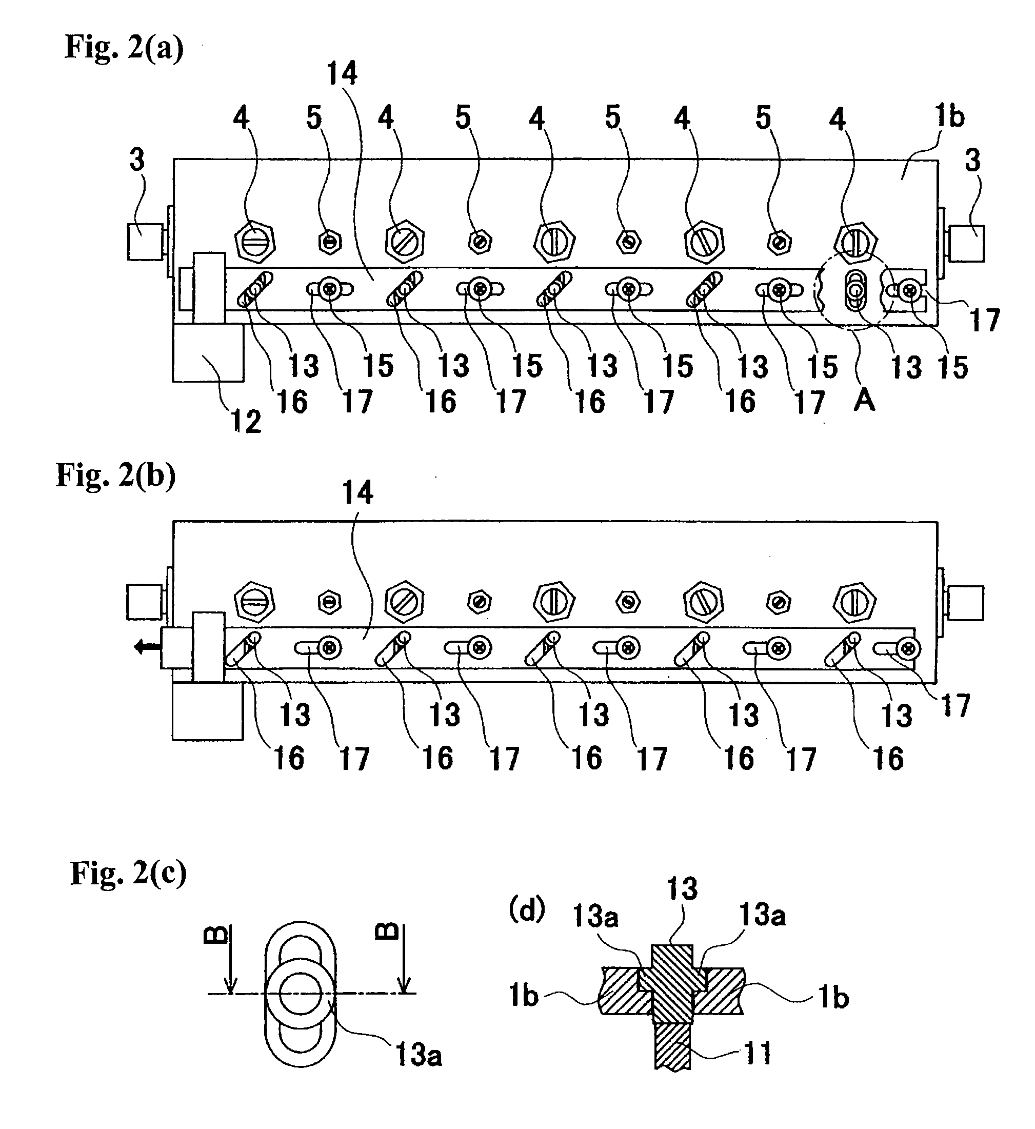
[0019] Further, by movably coupling the holders to the coupling member, the perturbation amount may be varied in each of the resonators by way of a cam structure or the like. Owing to this, even if the filter is configured by continuously arranging resonators having resonant cavities with different profiles , the displacement amount of each of the dielectrics may be individually varied among the resonators. Therefore, since the variation amounts of the frequencies may be arbitrarily set for the resonators, respectively, with the tunable filter, deterioration of the filter characteristics may be restrained, and the center frequency may be freely selected.
[0020] Since the perturbation due to the dielectric is applied to the electric field in the resonant cavity, the decrease in Q of the resonator may be minimized by using a dielectric having a good dielectric loss tangent. In addition, since it is not necessary to use an active element such as a PIN diode in a resonant cavity to which extremely high current is applied, power resistance characteristics of the filter can be enhanced, thereby increasing reliability. Further, since it would be unnecessary to attach an excessive component like a PIN diode or a ground line combined with a PIN diode to the filter, there is provided a tunable filter in which intermodulation due to such excessive component does not occur.
[0021] With the third aspect of the invention, since the perturbation due to the displacement of the dielectric bar is not applied to the region where the adjacent resonators are electromagnetically coupled, the variation in relation to the coupling coefficients provided between the stages is suppressed while only the frequencies are varied. Accordingly, there is provided a tunable band pass filter in which a return loss waveform is less disordered.
[0022] With the fourth and fifth aspects of the invention, the insertion amounts, with respect to the cavities, of the dielectrics which allow the frequencies to be varied, can be determined appropriately. Accordingly, even when the filter has resonators having different cavity profiles or resonators having different sensitivities of the perturbation of the resonant frequencies with respect to the positional displacement of the dielectrics, the insertion amounts of the dielectrics may be pre-adjusted such that the perturbation amounts of the resonant frequencies become the same. In addition, the mechanism can be applied to fine adjustment of the frequencies during adjustment of the filter.

Problems solved by technology

In addition, in this configuration, since frequencies are varied according to the on / off state of the PIN diodes, a center frequency of the band pass filteror band elimination filter is varied only discretely, and may not be varied steplessly.
Accordingly, the PIN diodes may be burned out, and the filter may be no longer usable.
Similarly, when the filter needs to pass electricity as high as several watts to several tens of watts, the PIN diodes, and the combination of the ground lines and the PIN diodes may cause a high level of intermodulation to occur.

Method used


Image

  • Tunable filter, duplexer and communication apparatus
  • Tunable filter, duplexer and communication apparatus
  • Tunable filter, duplexer and communication apparatus

Examples


first embodiment

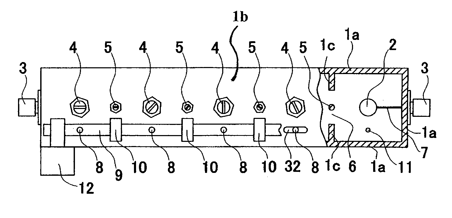
[0037] On the basis of the above-described configuration, the first embodiment functions as a 5-stage band pass filter. Note that the number of stages may be determined as a design matter, with respect to desired characteristics.

[0038] A elongated hole 32 is provided in the outer conductor 1b for each cavity, and a holder 8 is inserted into the elongated hole 32 movably, in the horizontal direction in the drawing. An end of the holder 8 projects out of the outer conductor 1b, and fixed to a coupling member 9. A dielectric bar 11 is attached to the other end of the holder 8. A material of the coupling member 9 and the holder 8 may be appropriately selected from resin, metal, ceramic, and the like. The dielectric bar 11 may be fixed to the holder 8 by bonding, press-fitting, caulking, mechanical fixing, or by a combination of these, for example. The profile, the length, the dielectric constant, and the like, of the dielectric bar 11 may be appropriately determined. The profile of the ...

fourth embodiment

[0060] Referring to FIG. 4, the present invention is described. FIG. 4(a) is a plan view showing a 5-stage band elimination filter to which the present invention is applied, and shows the inner space of the filter with a part of an outer conductor 22b eliminated. FIG. 4(b) is a lateral view of FIG. 4(a), and shows the inner space of the filter with a part of an outer conductor 22a eliminated. FIG. 4(c) is an enlarged view taken along a line d-d shown in FIG. 4(b).

[0061] Inner conductors 23 are fixed on a bottom surface of the outer conductor 22a. Each inner conductor 23 may be integrally formed with the outer conductor 22a, or may be fixed at the bottom surface of the outer conductor 22a with a screw. While the inner conductor 23 is shown as a cylinder, the inner conductor 23 may be a polygonal prism. The inner conductor 23 is not fixed on a surface, which faces the outer conductor 22a, of an outer conductor 22b. A frequency-adjusting screw 25 made from a conductor is screwed throug...


PUM


Abstract

Dielectrics fixed on holders respectively provided at semi-coaxial cavity resonator stages are movably inserted through an outer conductor. The holders projecting out of the outer conductor are coupled to a coupling member, and the coupling member is directed to slide or turn, so that distances between the dielectrics and the inner conductors of the resonators are varied, and accordingly frequencies of the resonators are varied at the same time. Accordingly, there is provided a tunable filter that avoids an increase in insertion loss, is high-power resistant, does not cause intermodulation, and allows a center frequency of the filter to be varied steplessly and quickly.

Description

CROSS-REFERENCE TO RELATED APPLICATIONS [0001] This is a continuation of PCT / JP2005 / 020810 filed Nov. 4, 2005, incorporated by reference. BACKGROUND OF THE INVENTION [0002] 1. Technical Field [0003] The present invention relates to a tunable filter, a duplexer, and a communication apparatus, using a semi-coaxial cavity resonator. [0004] 2. Background Art [0005] A filter allowing a center frequency thereof to be varied to a desired value according to an external control signal, is called a tunable filter. A typical example of the tunable filter may be a tuning frequency variable band pass filter as disclosed in Japanese Unexamined Patent Application Publication No. 9-284097. The filter has a plurality of short-circuit bars. Ends of the short-circuit bars are respectively fixed at a predetermined height on a lateral surface of an inner conductor bar of a semi-coaxial cavity resonator to be equally spaced, extended radially in the horizontal direction, and then bent substantially perpe...

Claims


Application Information

Patent Timeline
IPC IPC(8): H01P1/213H01P1/20
CPCH01P1/2053
Inventor WADA, TAKAYA
Owner MURATA MFG CO LTD
Learn More