Indicator, method of teaching massage operation and method of massage operation

a massage treatment and indicator technology, applied in the field of indicators, can solve the problems of significant differences in the effect, inability to improve blood flow, and ineffective treatment, and achieve the effect of reducing variation in technique and high effective massage treatmen

Inactive Publication Date: 2007-03-08
IMANISHI NOBUAKI +2
View PDF0 Cites 6 Cited by
  • Summary
  • Abstract
  • Description
  • Claims
  • Application Information

AI Technical Summary

Benefits of technology

[0023] In the method of teaching massage treatment of the present invention, the aforesaid illustrations displaying the anatomical characteristics of the skin are used as teaching materials. No such illustrations were available anywhere in the world until now. By using such illustrations for explaining massage treatment, providers of massage treatment is made to understand the actual state of blood flow at locations near the skin surface and highly effective massage treatment is taught. Besides, this way of teaching massage treatment reduces variation in the technique among individual massage givers, because the fundamental points of the treatment are understood easily.

Problems solved by technology

However, effectiveness of the treatment differs significantly, depending on the skill of a massage giver, and certain aspects of mechanisms through which the effects of the treatment are manifested are not understood.
However, blood flow cannot be improved by simply applying physical pressure on blood vessels because the blood vessels are elastic and because valves in them would stop the flow of blood.
In applying such procedures also, there is significant difference in the effects, depending on the skill of a person applying them, and there seem to be many hidden factors that affect effectiveness of massage.
However, it can be said that almost nothing is known about mechanisms of blood flow control, such as locations of valves in the veins, and even the approximate paths of blood flow.
Besides this, no one has even imagined that the actual conditions of normal blood flow near the skin surface would significantly affect correct massaging technique and the effects of massage treatment.
Furthermore, no attempts at all have been made to closely examine the actual conditions of blood flow and to use information about the actual conditions for guiding and teaching of massage treatment.

Method used


Image

  • Indicator, method of teaching massage operation and method of massage operation
  • Indicator, method of teaching massage operation and method of massage operation
  • Indicator, method of teaching massage operation and method of massage operation

Examples


embodiment 1

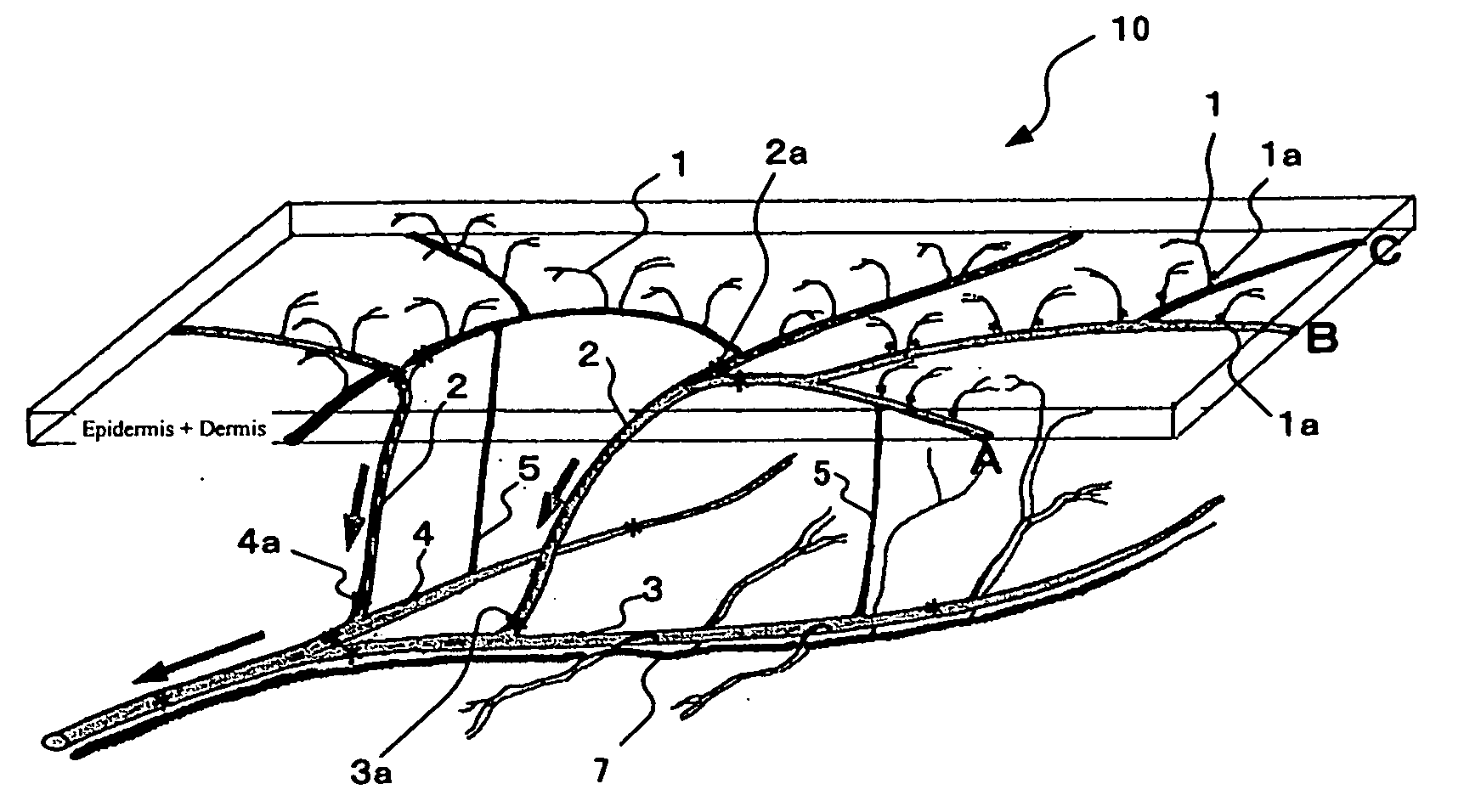
[0051]FIG. 1 is a first illustration 10 of Embodiment 1. It shows cutaneous veins in the part from the superficial part of the skin to the deep subcutaneous region, and valves in the veins. In this Embodiment 1, the first illustration 10 shows a vein (accompanied vein 3) accompanied by an artery 7 and a vein (unaccompanied vein 4) not accompanied by an artery. It also shows that most of the unaccompanied veins 4 form a venous plexus (the part including vessels A, B and C of FIG. 1) of comparatively large diameter veins, immediately below the dermis (or in the deep dermis). It also shows the presence of valves 1a (marked with asterisks in the Fig.)—which prevent reverse flow (in a distal direction) of blood from the region of the venous plexus immediately below the dermis (or in the deep dermis)—at the bases of thin vessels 1 ascending from the venous plexus located immediately below the dermis (or in the deep dermis) towards the superficial part of the skin.

[0052] On the other hand...

embodiment 2

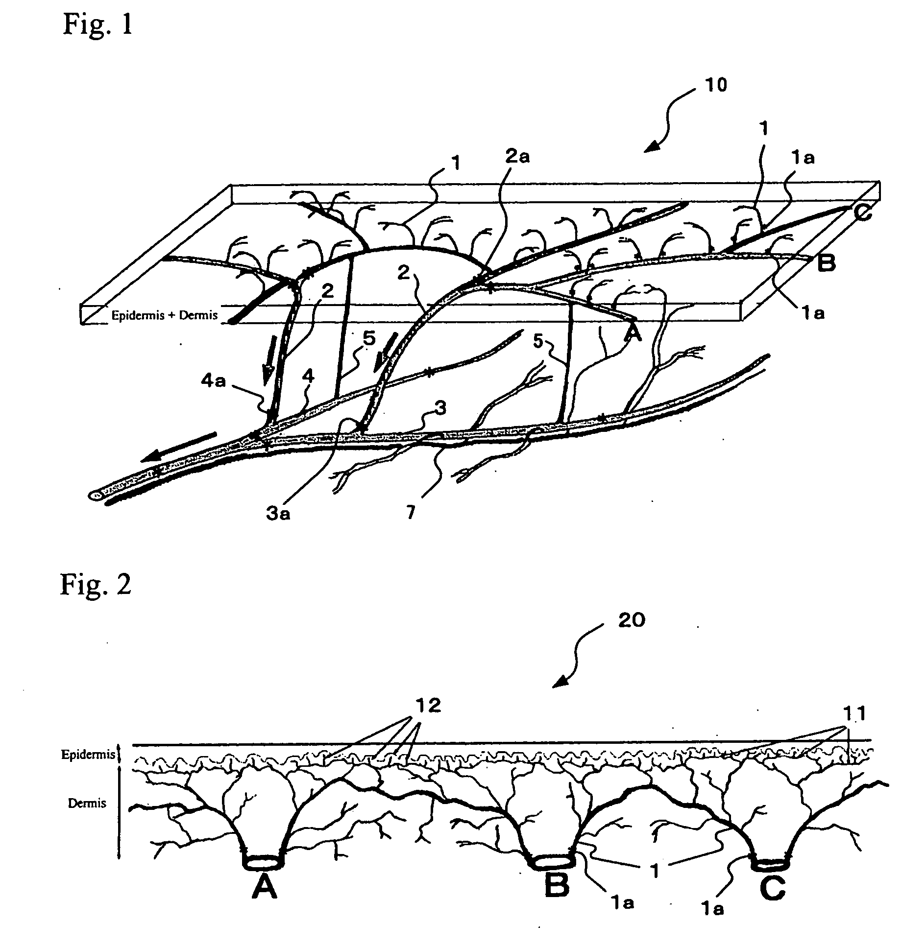
[0055]FIG. 2 shows the 2nd illustration, as a second embodiment of the invention, and is an enlarged view of the anatomical characteristics of the skin, including the position and state of the epidermis, dermis and veins in the region immediately below the dermis, and the valves in these veins shown in the illustration 10 of FIG. 1. In this Embodiment 2, an illustration 20 of FIG. 2 shows a number of thin vessels 1 ascending towards the epidermis from the vessels (A, B and C) of the venous plexus immediately below the dermis (or in the deep dermal layer), and branching and spreading immediately below the epidermis. It also shows that thinner vessels 11 arising from a number of these thin vessels 1 form a plexus immediately below the epidermis, and even thinner vessels 12 form a venous plexus towards the epidermal papillae. In other words, it shows that the unaccompanied veins, which do not run side-by-side with arteries, are immediately below the dermis (or in the deep dermal layer)...

embodiment 3

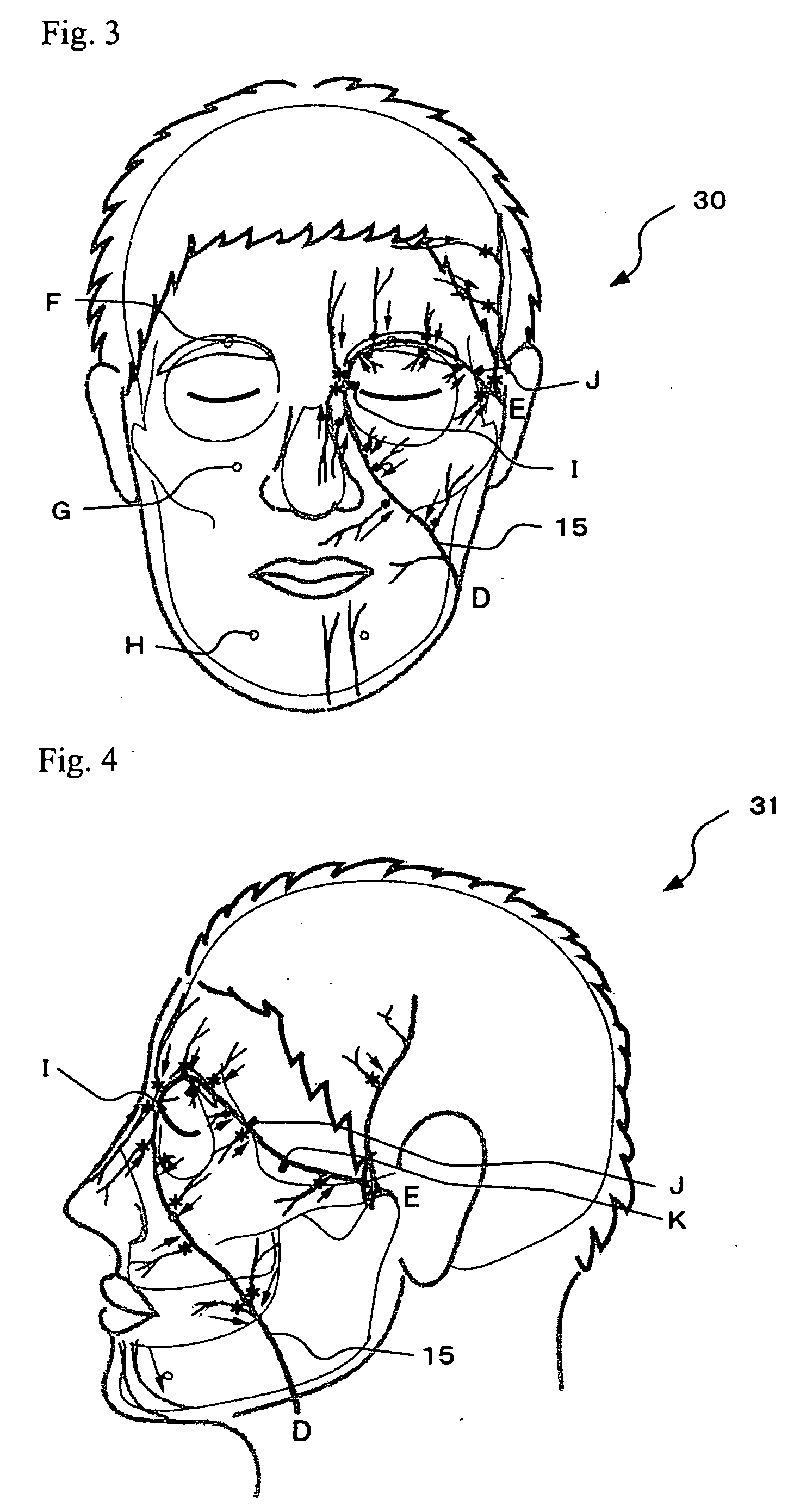
[0057]FIGS. 3 and 4 are of 3rd illustrations of Embodiment 3, which show the position and state of cutaneous veins and the valves in these veins, on an external view of a face, as an example of the whole or a part of the human body. This Embodiment 3 includes an illustration 30 (a front view of the face) and an illustration 31 (a side view of the face) as 3rd illustrations. These 3rd illustrations 30 and 31 are useful because they can be used, along with the 1st illustration 10 and the 2nd illustration 20, as a basis for explaining a method of massage treatment of the face.

[0058] The 3rd illustrations 30 and 31 will be explained below in greater detail.

[0059] The 3rd illustration 30 (a front view of the face) and the 3rd illustration 31 (a side view of the face) display a roughly U-shaped vein 15 running from a point D on the neck to a point E at the root of the earlobe, looping around the orbit. This vein 15 that is roughly in the shape of an inverted U (referred to as “roughly U...


PUM


Abstract

This invention provides illustrations that can be used as educational materials for teaching massage treatment, dermatological therapeutic techniques, dermatological diagnostics, etc.; and methods of performing and teaching massage treatment, based on new anatomical findings about cutaneous blood vessels. The illustrations have a 1st illustration, which displays anatomical characteristics of the skin, including the position and state of the cutaneous veins and valves within the veins. The method of teaching the massage treatment uses the aforesaid illustrations as teaching materials. The massage treatment includes a procedure (A) that comprises pressing, towards their respective plexuses, the thin vessels ascending from the deep dermal venous plexus and/or the subdermal venous plexus, which are formed in the deep dermal layer and/or immediately below the dermis by veins unaccompanied by arteries.

Description

FIELD OF THE INVENTION [0001] The present invention relates to illustrations, methods of teaching massage treatment, and methods of massaging. To be more specific, the present invention relates to illustrations that can be used as educational materials for teaching not only massage treatment but also dermatological therapeutic techniques, dermatological diagnostics, etc., and methods of teaching massage treatment and giving massage treatment using such illustrations. BACKGROUND OF THE INVENTION [0002] Massage is a cosmetic treatment that involves manual manipulation of the skin, and it is known to yield beneficial effects like improving stagnant blood flow, generating a feeling of well-being, and reducing swelling. However, effectiveness of the treatment differs significantly, depending on the skill of a massage giver, and certain aspects of mechanisms through which the effects of the treatment are manifested are not understood. Therefore, efforts are now being made to standardize t...

Claims


Application Information

Patent Timeline
Patent Type & Authority Applications(United States)
IPC IPC(8): G09B23/28G09B23/30
CPCG09B23/30
Inventor IMANISHI, NOBUAKINAKAJIMA, HIDEOTOUGOU, JUNKO
Owner IMANISHI NOBUAKI
Why Eureka
Try Eureka