Apparatus and method for continuous separation of magnetic particles from non-magnetic fluids

Inactive Publication Date: 2007-03-15
RES USA LLC
View PDF3 Cites 24 Cited by
  • Summary
  • Abstract
  • Description
  • Claims
  • Application Information

AI Technical Summary

Benefits of technology

[0013] The slurry may be comprised of both magnetic and non-magnetic particles suspended in a non-magnetic fluid. The elevation at which the slurry flow is released into the separation chamber is adjusted so as not to stir up particles which have concentrated in the bottom of the separation chamber where magnetic particles exit the apparatus. Non-magnetic particles and fluid follow the lines of flow and exit at the top and the bottom of the apparatus in relation to the rates of flow. The bottom of the chamber extends below the bottom edge of the magnet return frame and is sloped to a final exit diameter outside of the magnetic field region. This slope is introduced to minimize effects such as frictional drag which would tend to hold the magnetic particles inside the separation chamber. An overflow outlet port is located at the top of the chamber where non-magnetic fluid and some parti

Problems solved by technology

418-425 (September, 1976)] is not well suited to the Fischer-Tropsch application because of the strongly magnetic character of the catalyst particles employed.
Additionally, the concentration of these particles in the wax-rich overflow from the reactors employed is so high that the batch process and quasi-continuous versions of it are plugged with the catalyst too rapidly for commercial application.
No means are employed to control the rate of flow of the two streams exiting the coalescer.
This results in a possible buildup of catalyst particles in the bottom of the chamber which can lead to plugging.
While this results in strong magnetic force

Method used


Image

  • Apparatus and method for continuous separation of magnetic particles from non-magnetic fluids
  • Apparatus and method for continuous separation of magnetic particles from non-magnetic fluids
  • Apparatus and method for continuous separation of magnetic particles from non-magnetic fluids

Examples


Example

EXAMPLE 1

Typical Experiment

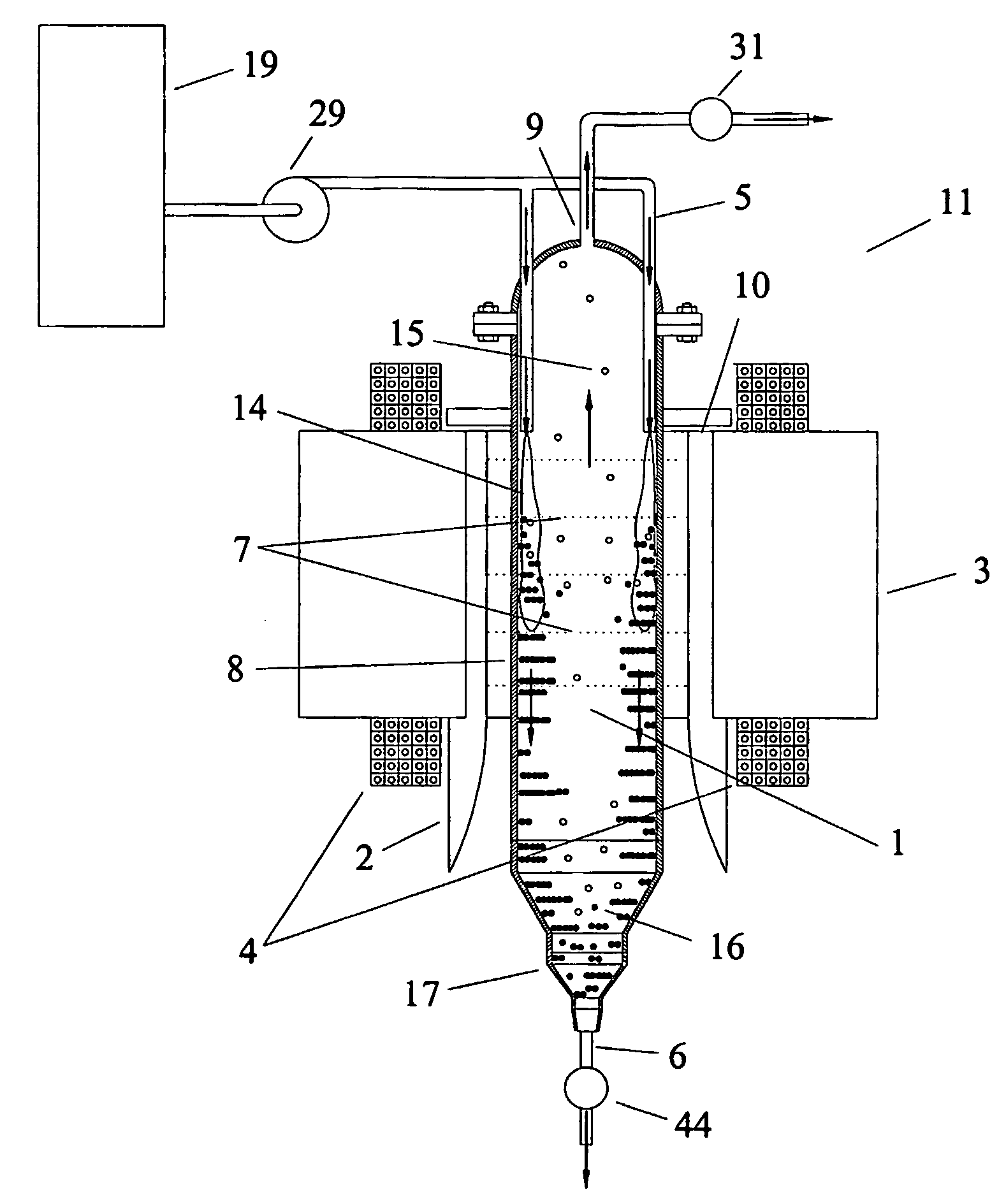
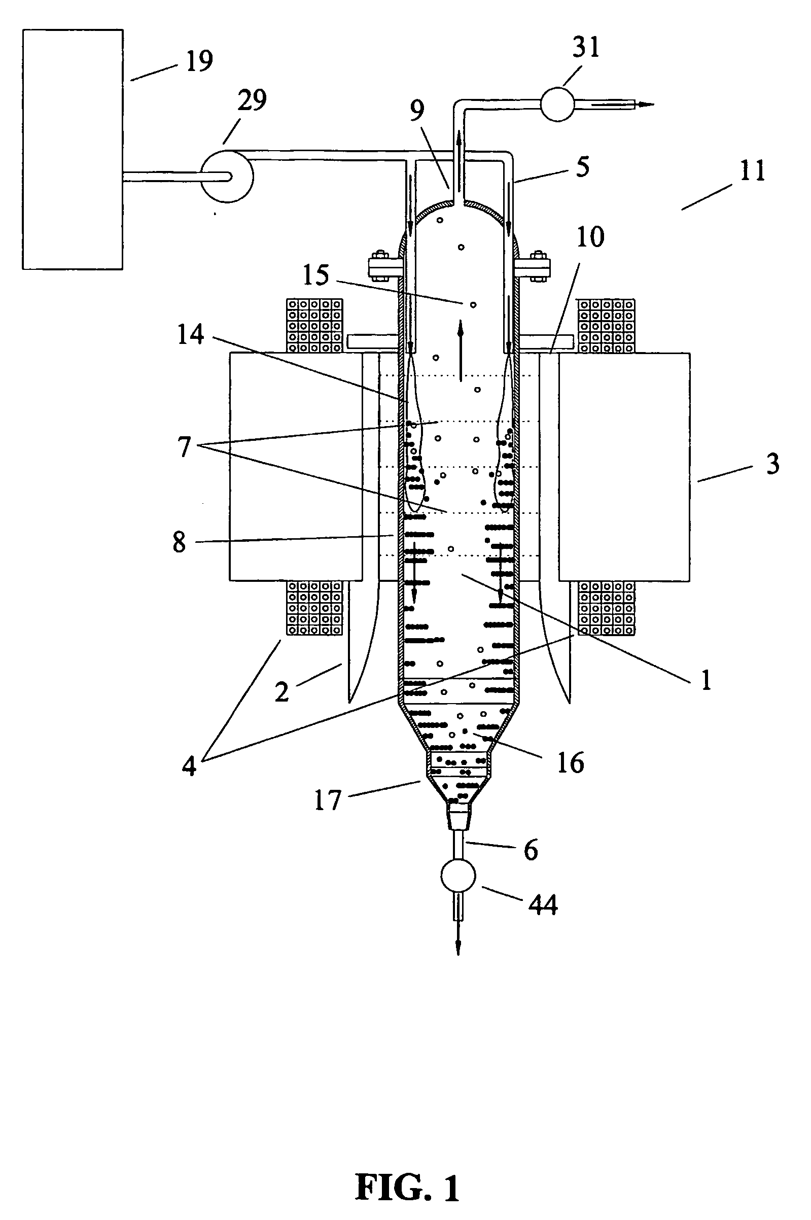
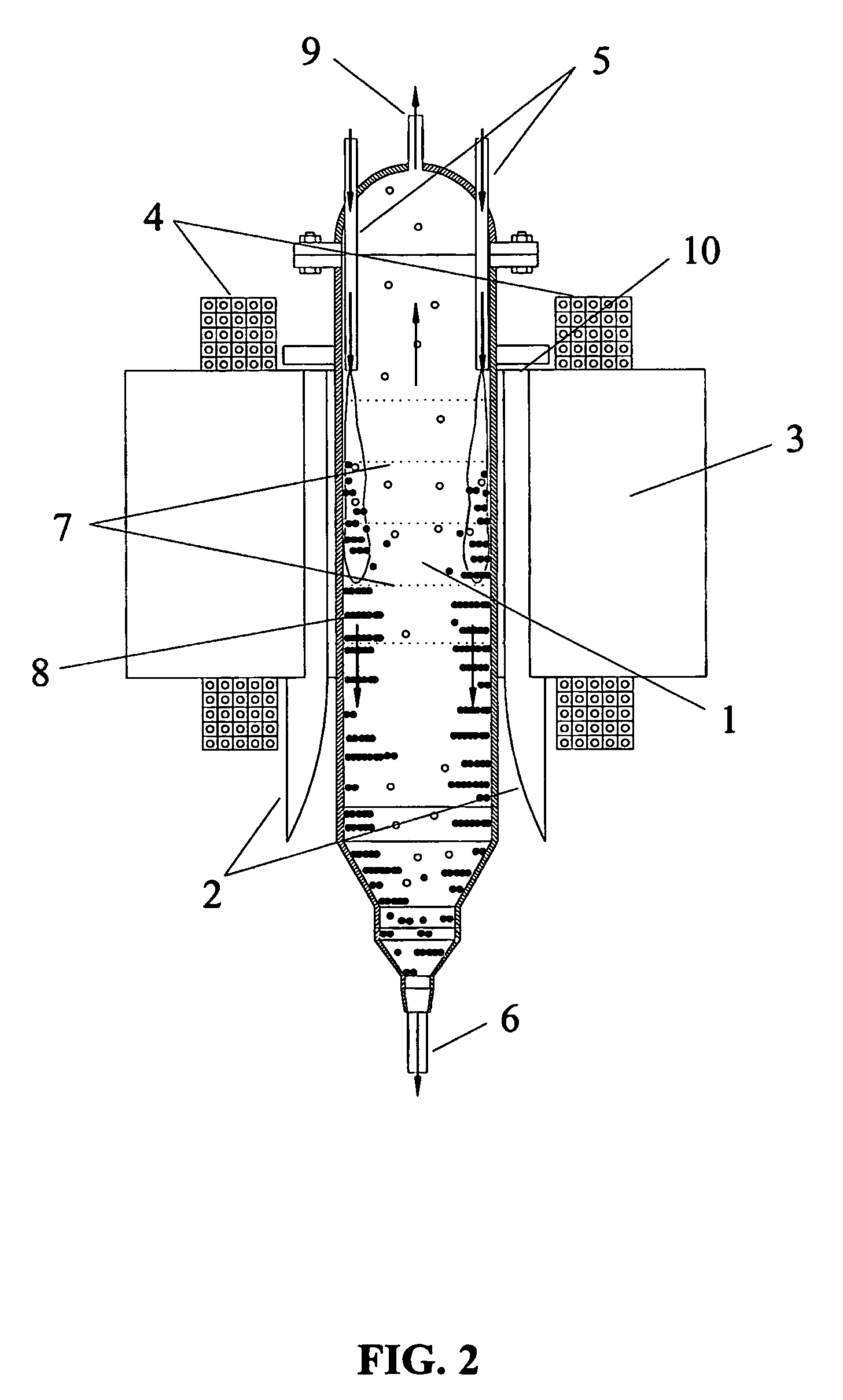
[0052] A slurry containing 21.45 wt. % catalyst was fed at the rate of 17.53 gpm into a 6-inch diameter separation vessel through two sets of down-directed feed lines located across from one another next to the elongated tapered poles of the electromagnet. A vessel with a 6-inch inside diameter was employed. The overall canister length was 21 inches from the top of the dome at the overflow port to the bottom of the straight section which terminated 5 inches below the bottom of the magnet return frame. The volume of the six inch canister is 10 liters. Each set of feed lines consisted of one ¾-inch outer diameter tube and two ½-inch tubes on either side of the ¾-inch inlet. The magnetic field was 2000 gauss. The underflow was withdrawn through a 2-inch pipe (nominal 2.067 inch inner diameter) at a rate of 16.1 gpm and contained 23.33 wt. % ash. The overflow was withdrawn through a 12-inch tube with 0.035-inch wall thickness at the rate of 1.43 gpm and cont...

Example

EXAMPLE 2

Magnetic Field Effects

[0055] The slurry was fed at an average rate of 11.3 gpm to a 6 inch diameter vessel through two ¾-inch outside diameter down-directed stainless pipes located next to the inside walls of the separation chamber adjacent to the magnet poles as described above. The pipe outlets open into the separation chamber at an elevation which is 3 inches below the top of the electromagnetic return frame. The opening at the chamber overflow was ½-inch tubing; the opening at the underflow was nominally 1-inch pipe. The magnetic field strength was varied from the locked-in field of the electromagnet with no current in the energizing coils up to 2200 gauss. Values were used to maintain a recycle ratio of approximately 11:12. The ash levels in the feed, underflow, and the overflow were measured. The percentage reduction in ash was calculated as % reduction=[(ash in feed−ash in overflow) / ash in feed]*100. Results are given versus the applied magnetic field in Table I. ...

Example

EXAMPLE 3

Flow Entrance Effects

[0057] The direction in which the slurry is introduced into the separation vessel is important. This is illustrated with measurements made using a 2-inch diameter separation vessel and shown in Table II. All measurements were made at 1000 gauss magnetic field strength. TABLE IIEffects of Flow Entry DirectionOverflowUnderflowFeedFlow RateAshFlow RateAshFlow RateAshRecycleAsh Reduction(gpm)(wt %)(gpm)(wt %)(gpm)(wt %)Ratio(wt %)Tangential0.0120.970.17421.380.1920.0314.195.1Tangential0.0060.940.18219.870.1919.2630.395.1Down-Directed0.0410.940.25822.180.3019.306.495.2Down-Directed0.0400.860.31420.720.3518.488.095.4

[0058] Two flow configurations are shown, tangential and down-directed. In the tangential case, one ¼-inch inner diameter entry port is employed. It is located 3 inches above the bottom of the iron return frame of the electromagnet and makes a tangential entry into the separation vessel at 90 degrees with respect to the electromagnet poles. For...


PUM

PropertyMeasurementUnit
Lengthaaaaaaaaaa
Flow rateaaaaaaaaaa
Diameteraaaaaaaaaa

Abstract

A magnetic separator vessel (1) for separating magnetic particles from non-magnetic fluid includes a separation chamber having an interior and exterior wall, a top and bottom portion; a magnet (3) having first and second poles (2) positioned adjacent to the exterior wall, wherein the first pole is substantially diametrically opposed to the second pole; a inlet port (5) is directed into the top portion of the separation chamber, wherein the inlet port (5) is positioned adjacent to one of the first and second poles (2), wherein the inlet port (5) is adapted to transfer a mixture into the separation chamber; an underflow port (6) in communication with the bottom portion, wherein the underflow port (6) is adapted to receive the magnetic particles; and an overflow port (9) in communication with the separation chamber, wherein the overflow port (9) is adapted to receive the non-magnetic fluid.

Description

STATEMENT REGARDING FEDERALLY SPONSORED RESEARCH [0001] This invention was made with Government support under Grant DE-FG02-00ER83008, awarded by the U.S. Department of Energy. The Government has certain rights in this invention.BACKGROUND OF THE INVENTION [0002] 1. Field of the Invention [0003] This invention relates to the art of continuous separation of magnetic particles from a non-magnetic fluid; more specifically it relates to the continuous separation of such types as they pass through a uniform applied magnetic field; and more specifically it relates to the continuous separation of sub-micron size magnetic particles from viscous flows such as the continuous separation of magnetic catalysts from Fischer-Tropsch wax at operating temperature and pressure or separation of particles of wear from transformer oil or spent engine oil and other non-magnetic hydrophobic or hydrophilic liquids. [0004] 2. Description of Related Art [0005] U.S. Pat. No. 4,605,678 describes the applicatio...

Claims


Application Information

Patent Timeline
IPC IPC(8): C02F1/48C07C27/06B03C1/0355
CPCB03C1/0355B03C1/288C02F1/488C10G32/02C10G2/342C10G31/09C02F2103/365
Inventor ODER, ROBIN R.JAMISON, RUSSELL E.
Owner RES USA LLC
Why Eureka
Try Eureka