Light guide plate for keypad backlight panels and method of manufacturing the same

a technology of backlight panels and light guides, which is applied in the direction of optical elements, planar/plate-like light guides, instruments, etc., can solve the problems of power consumption, reduced operating time of batteries, and difficult to manufacture led keypad modules in slim structures, etc., and achieves high brightness

Inactive Publication Date: 2007-03-15
MYT INC
View PDF5 Cites 45 Cited by
  • Summary
  • Abstract
  • Description
  • Claims
  • Application Information

AI Technical Summary

Benefits of technology

[0012] Therefore, the present invention has been made in view of the above problems, and it is an object of the present invention to provide a light guide plate for keypad backlight panels that can be manufactured in a slim structure, can uniformly supply light having high brightness in a face illuminating fashion even through a small number of light sources are used, or can supply light to a desired region in a spot illuminating fashion, and a method of manufacturing the same.

Problems solved by technology

However, it is practically difficult to manufacture the LED keypad module in a slim structure although chip-type LEDs are used for the LED keypad module.
Also, using a large number of LEDs increases the power consumption due to the light emission from the LEDs, and therefore, the operating time of a battery is reduced.
However, the service life of the EL sheet 40 is shorter than that of each LED, the EL keypad module generates noise against an LCD module, and the reliability of the EL keypad module is decreased.
Furthermore, the manufacturing costs of the EL keypad module are higher than those of the LED keypad module.
However, this light guide plate 60 is basically made of silicone, and therefore, it is not possible to manufacture the light guide plate 60 in a slim structure.
Furthermore, application of the light guide plate 60 is practically difficult.

Method used


Image

  • Light guide plate for keypad backlight panels and method of manufacturing the same
  • Light guide plate for keypad backlight panels and method of manufacturing the same
  • Light guide plate for keypad backlight panels and method of manufacturing the same

Examples


Embodiment Construction

[0030] Now, preferred embodiments of the present invention will be described in detail with reference to the accompanying drawings.

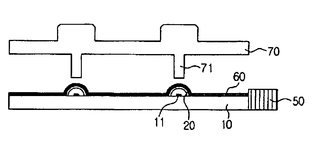
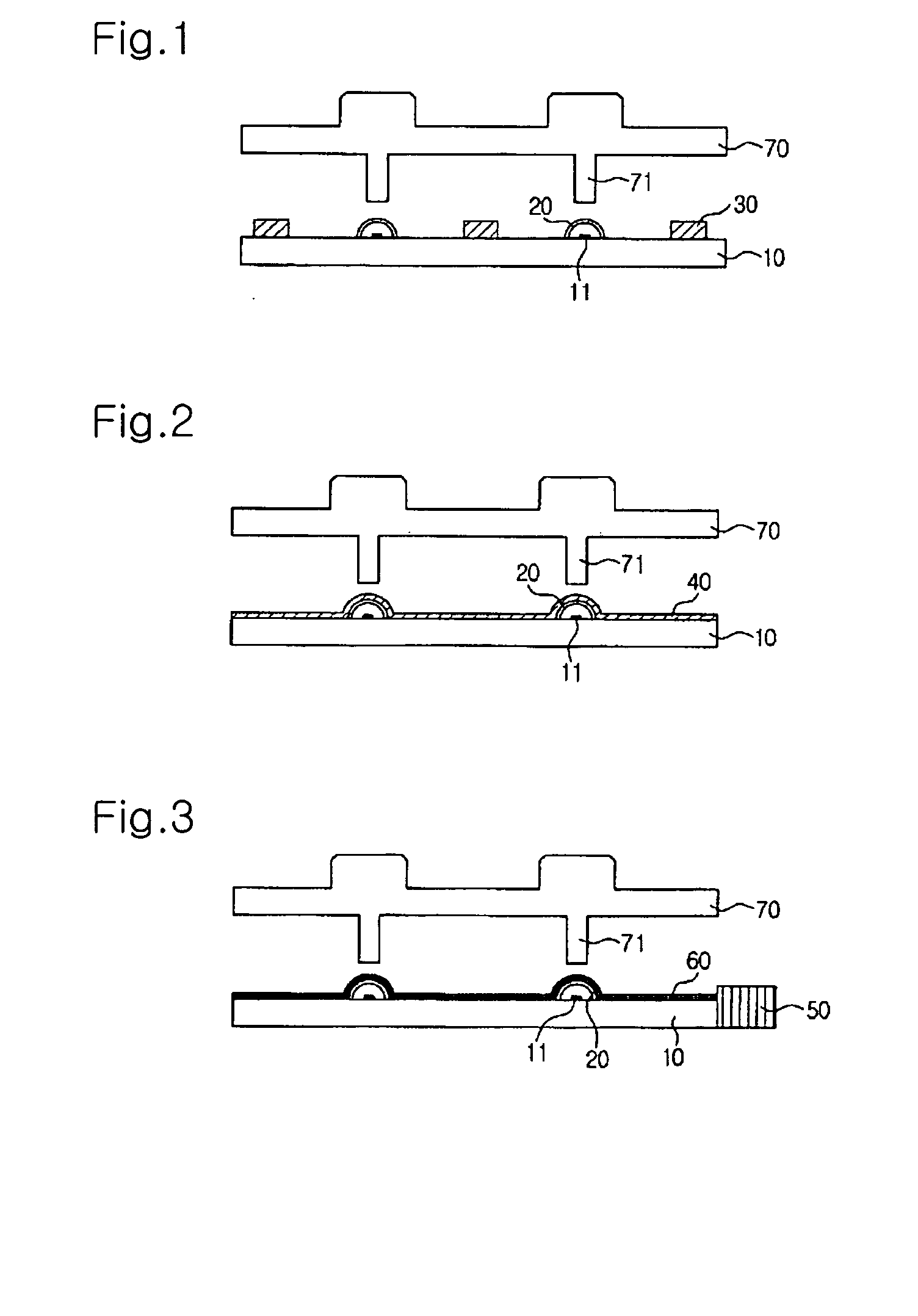
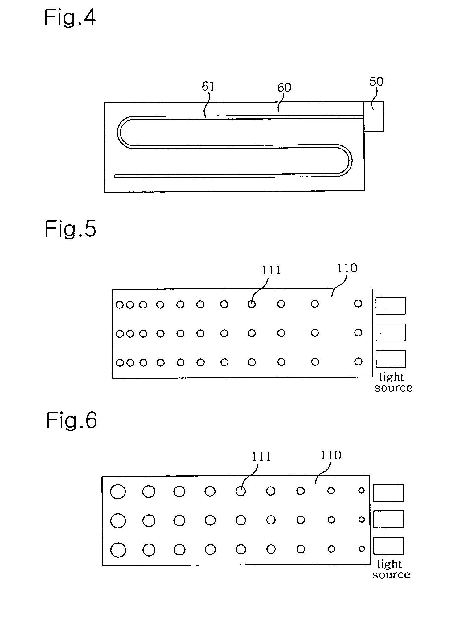
[0031]FIG. 5 is a view illustrating a light guide plate 110 for keypad backlight panels according to a first embodiment of the present invention, FIG. 6 is a view illustrating a light guide plate 110 for keypad backlight panels according to a second embodiment of the present invention, FIG. 7 is a view illustrating a light guide plate 110 for keypad backlight panels according to a third embodiment of the present invention, FIG. 8 is a view illustrating a light guide plate 110 for keypad backlight panels according to a fourth embodiment of the present invention, FIG. 9 is a view illustrating a light guide plate 110 for keypad backlight panels according to a fifth embodiment of the present invention, and FIG. 10 is a graph illustrating pattern density distribution of the light guide plate 110 for keypad backlight panels according to the present invention....


PUM


Abstract

Disclosed herein is a light guide plate for keypad backlight panels, which is mounted at the rear of a keypad having numerals or characters printed thereon for supplying light emitted from a light source mounted at one side of the keypad to the keypad. The light guide plate is made of polycarbonate and is provided at the rear surface thereof with a concave-convex pattern, the density of which is increased as pattern elements of the pattern become more distant from the light source, such that light emitted from the light source is reflected and is uniformly supplied to the keypad, the pattern being formed on the light guide plate by hot stamping, injection molding, or micro blasting. The density of the pattern is adjusted by adjusting the distance between the pattern elements of the pattern or by adjusting the size of the pattern elements of the pattern. Consequently, it is possible to manufacture a keypad module in a slim structure or a curved structure. It is also possible to manufacture a keypad module that is capable of uniformly supplying light.

Description

BACKGROUND OF THE INVENTION [0001] 1. Field of the Invention [0002] The present invention relates to a light guide plate for keypad backlight panels, and, more particularly, to a light guide plate for keypad backlight panels, which is mounted at the rear of a keypad for supplying light emitted from a light emitting device to the keypad, and a method of manufacturing the same. [0003] 2. Description of the Related Art [0004] Generally, a keypad module is used as a switch apparatus which is mounted in electronic equipment, such as mobile phones, remote controls, and personal digital assistants (PDAs), to generate signals or to perform various additional functions. The keypad module includes an additional illuminating apparatus which is used to distinguish numerical keys or character keys at night or in a dark place. [0005]FIG. 1 is a sectional view illustrating a conventional direct illumination type light emitting diode (LED) keypad module. As shown in FIG. 1, the keypad module includ...

Claims


Application Information

Patent Timeline
Patent Type & Authority Applications(United States)
IPC IPC(8): G06C7/02
CPCG02B6/006G02B6/0036H04M1/22
Inventor LEE, MIN-KYU
Owner MYT INC
Why Eureka
Try Eureka