Eccentric thrust bearing assembly and a wheel with built-in suspension using the same

a technology of eccentric thrust bearing and bearing assembly, which is applied in the direction of elastic bearings, couplings, transportation and packaging, etc., can solve the problems of not being able being difficult to incorporate the conventional double-row eccentric thrust bearing assembly into the wheel, and being difficult to accommodate the bearing assembly in a very limited internal space of the wheel. , to achieve the effect of reducing the radial width of the inner race, reducing the radial width

Inactive Publication Date: 2007-03-15
JTEKT CORP +1
View PDF6 Cites 14 Cited by
  • Summary
  • Abstract
  • Description
  • Claims
  • Application Information

AI Technical Summary

Benefits of technology

[0045] It is further preferred that a relatively movable range provided by a radial gap between the axially outside member and the axially inside member substantially corresponds to the movable range of the rolling element confined by the rolling-element guide. In such a constitution, when the axially inside member and the axially outside member are relatively moved so far as to eliminate the radial gap therebetween, the rolling elements are moved so far as to substantially eliminate the respective gaps between themselves and the rolling-element guide. That is, when the axially inside member and the axially outside members are relatively moved across the whole relatively movable range therebetween, the rolling elements are also moved across the whole movable ranges thereof. Accordingly, the excessive space between the axially inside member and the axially outside member is eliminated or minimized. Thus, the bearing assembly may be downsized and may attain the increased decenterable range.
[0046] It is further preferred that the rolling-element guide has an annular shape and is formed with three or more movable-range delimiting holes arranged on the same circle with equal circumferential spacing, whereas one rolling element is disposed in each of the movable-range delimiting holes. In such a constitution, the rolling elements disposed in the respective movable-range delimiting holes are uniformly arranged in the circumferential and radial directions, so that the bearing assembly is adapted to bear the axial loads and the moment load in a more stable manner. Since only one rolling element is disposed in each movable-range delimiting hole, the rolling elements are prevented from contacting each other to cause friction.
[0047] It is further preferred that a radially movable distance of the rolling element confined by the rolling-element guide substantially corresponds to a radial width of the inner race or the outer race. Such a constitution may minimize the radial width of the inner race or the outer race. This leads to the reduction of the weight and cost of the bearing assembly.
[0048] A wheel with built-in suspension according to the invention comprises the above double-row eccentric thrust bearing assembly and the elastic member which are interposed between the outside wheel member and the inside wheel member, the bearing assembly permitting an eccentric relative movement between the wheel members while bearing axial loads applied between the wheel members. In such a wheel, the suspension is accommodated in the wheel and hence, the suspension mounting space externally of the wheel may be reduced accordingly. What is more, the wheel may also be reduced in unsprung weight. In addition, the wheel is adapted to bear the axial loads, making the wheel featuring the practical utility.
[0049] In a case where the wheel with built-in suspension further comprises a damper interposed between the outside wheel member and the inside wheel member, the suspension is equipped with the damper additionally to the elastic member, so that the expansion / contraction of the elastic member may be quickly damped.

Problems solved by technology

However, it is never easy to incorporate the conventional double-row eccentric thrust bearing assembly into the wheel.
However, the conventional double-row eccentric thrust bearing assembly has never been studied to define a proper gap between inside and outside members relative to a decenterable range of the bearing assembly, the gap provided for permitting an eccentric movement of the assembly.
As a result, it becomes impracticable to accommodate the bearing assembly in a very limited internal space of the wheel.
Furthermore, race portions of the conventional double-row eccentric thrust bearing assembly are great in size.
In cases, a machining process of the races may be extremely difficult, involving difficulty in ensuring the flatness of a raceway surface and such.
This leads to difficulty of fabricating a larger bearing assembly and to cost increase.
What is more, the race portion formed from an iron-base metal such as a bearing steel has such a large size that the bearing assembly is increased in weight or cannot accomplish weight saving.
Accordingly, the use of this bearing assembly in the wheel with built-in suspension results in the increase of the weight or cost of the wheel.
However, such double-row eccentric thrust bearing assemblies have various problems.
In the aforementioned case where the rolling elements are randomly disposed or arranged in the full-type ball bearing fashion, the rolling elements slidingly contact with one another to produce friction, which results in great resistance and great energy loss during operation.
In this case, however, the friction results from sliding contact between the cage and the race.
Such friction causes energy loss and heat of the bearing assembly operating as the suspension.

Method used


Image

  • Eccentric thrust bearing assembly and a wheel with built-in suspension using the same
  • Eccentric thrust bearing assembly and a wheel with built-in suspension using the same
  • Eccentric thrust bearing assembly and a wheel with built-in suspension using the same

Examples


first embodiment

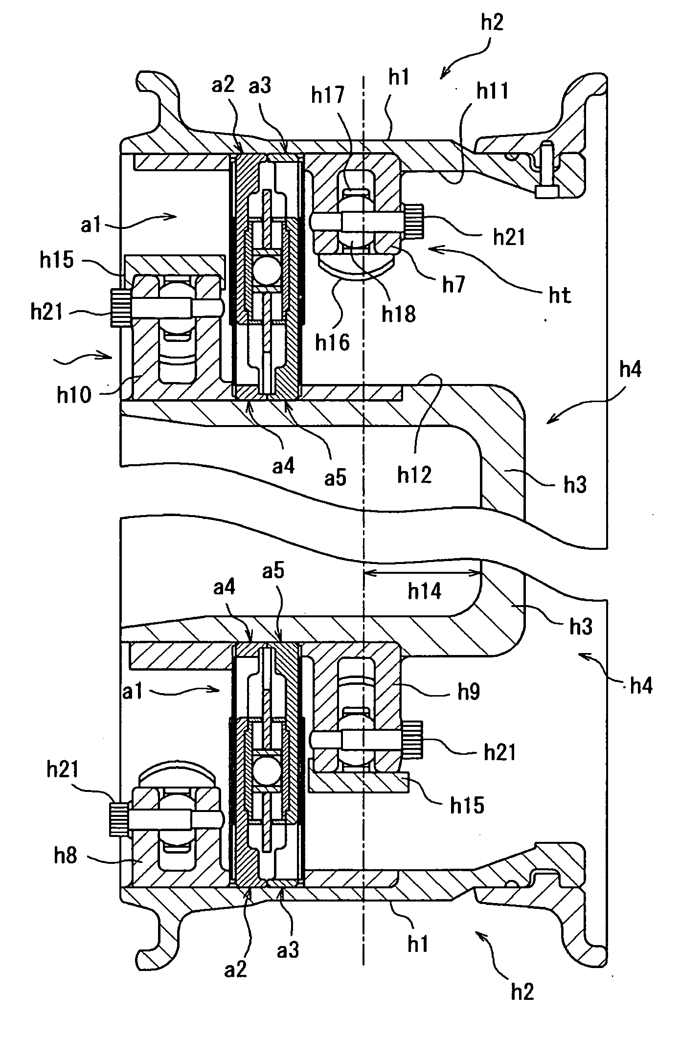
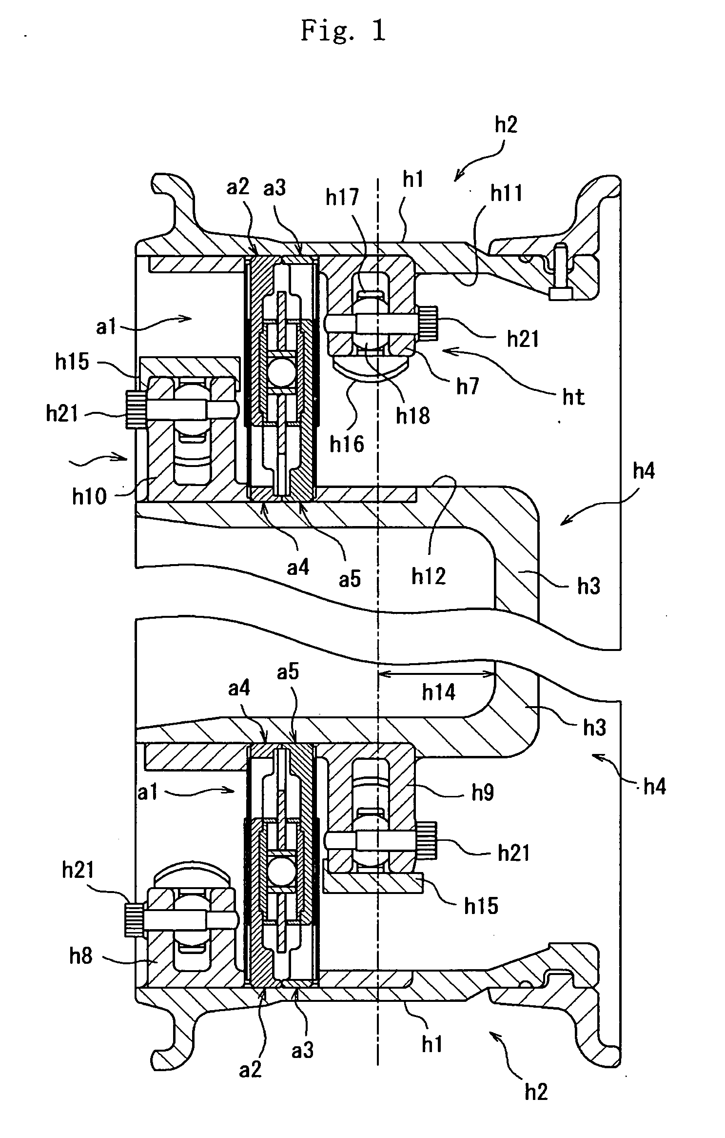
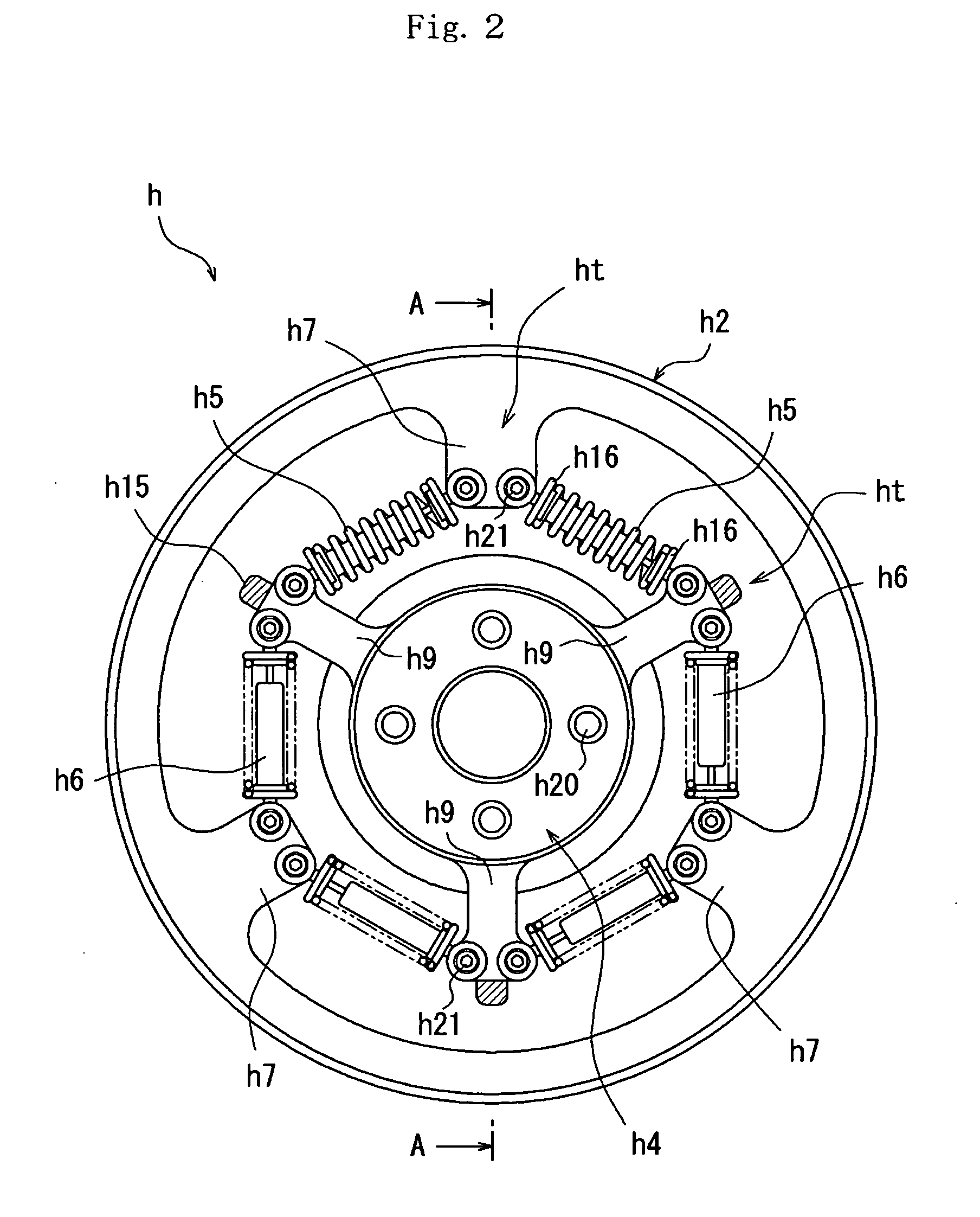
[0082] It is noted here that a position where the outside wheel member h2 is connected with the helical compression spring h5 is defined as an outside connection position. the forming positions of the front-side inward projection h7 and the back-side inward projection h8 are equivalent to the outside connection position. A position where the inside wheel member h4 is connected with the helical compression spring h5 is defined as an inside connection position. According to the embodiment, the forming positions of the front-side outward projection h9 and the back-side outward projection h10 are equivalent to the inside connection position. According to the embodiment, as described above, the circumferentially adjoining front-side inward projection h7 and front-side outward projection h9 (and the circumferentially adjoining back-side inward projection h8 and back-side outward projection h10 not shown) are interconnected by means of the helical compression spring h5 and the damper h6. ...

second embodiment

[0136]FIG. 9 is a perspective view of the bearing assembly b1 according to the The perspective view is an exploded perspective view wherein one of the two axially outside cases 2 of the bearing assembly b1 is disassembled therefrom. Furthermore, the view omits the delineation of a part of the assembly in the interest of easy view of an internal structure of the bearing assembly b1. FIG. 10 is a sectional view of the bearing assembly b1 (the lower half from its axis is omitted), a circumferential position of which is defined to be a position on a line passing through the centers of balls b6 as the rolling elements. FIG. 11 is a front view of a principal part (quadrant) of the bearing assembly as viewed along the arrows from section on the line A-A in FIG. 8.

[0137] As shown in FIG. 9 and FIG. 10, the bearing assembly b1 includes: two annular axially outside cases b2, b2 disposed in axially opposing relation; and an annular axially inside case b3 interposed between these two axially o...

sixth embodiment

[0193]FIG. 18 is an exploded perspective view showing a bearing assembly 40 according to the invention. FIG. 19 is a sectional view of the bearing assembly 40. This bearing assembly 40 does not posses the ring-like cage 9 as illustrated by the bearing assemblies 1 and such according to the embodiments shown in FIG. 14 to FIG. 17, but includes a rolling-element guide 19. However, some parts of this bearing assembly have structures common to those of the bearing assemblies 1 and such. Hence, those common parts are represented by the same reference characters as those in FIG. 14 and FIG. 15 showing the bearing assembly 1, respectively and the description thereof is dispensed with.

[0194] Specific differences between the bearing assembly 40 and the bearing assemblies 1 and such are as follows. The bearing assemblies 1 and such are provided with the ring-like cage 9 which rollably accommodates the balls 8 in the individual pocket holes 9a thereof so as to be moved in operative association...


PUM


Abstract

An eccentric thrust bearing assembly mounted in a wheel with built-in suspension including: an outside wheel member including a rim portion to which a tire is mounted; an inside wheel member including a disk portion coupled with an axle; and an elastic member interposed between the outside wheel member and the inside wheel member, the bearing assembly permitting an eccentric relative movement between the wheel members while bearing an axial load applied between the wheel members.

Description

TECHNICAL FIELD [0001] The present invention relates to a wheel with built-in suspension, which contains a suspension therein, and an eccentric thrust bearing assembly mountable in the wheel. BACKGROUND ART [0002] The suspension for use in automotive vehicles generally includes: an elastic member such as a spring; and a damper (shock absorber). The suspension plays a role of absorbing vibrations from the road surface as supporting a vehicle body. While various types of suspensions, such as a strut type and a wishbone type, are known in the art, each of the suspensions is not accommodated in the wheel but is mounted externally of the wheel. This requires a space for mounting the suspension, sacrificing the quality of vehicle interior comfort feature. Even though the strut type suspension having a relatively simple structure is employed, for example, a limited vehicle interior space is available because the spring and the shock absorber are present externally of the wheel and vertical...

Claims


Application Information

Patent Timeline
Patent Type & Authority Applications(United States)
IPC IPC(8): B60G9/00F16C19/30F16D3/62
CPCF16D3/62B60B9/24B60B9/06F16C19/10F16C27/06
Inventor TADA, SEIJIIMAMURA, TADASHI
Owner JTEKT CORP
Why Eureka
Try Eureka