Electron beam source for use in electron gun

Active Publication Date: 2007-03-15
APPLIED MATERIALS INC
View PDF23 Cites 10 Cited by
  • Summary
  • Abstract
  • Description
  • Claims
  • Application Information

AI Technical Summary

Problems solved by technology

It has generally been difficult to obtain very high beam currents focused into a small spot using Schottky electron sources.
Although the brightness of the emitter is high in such sources, the angular intensity of the electron beam emerging from the emitter region is limited by the properties of the emitter itself.
Using this approach, the emitter tip and the extraction region are immersed in a magnetic field, which results in a significant increase in the operating solid angle of emission compared to all-electrostatic systems.
Howe

Method used


Image

  • Electron beam source for use in electron gun
  • Electron beam source for use in electron gun
  • Electron beam source for use in electron gun

Examples


Embodiment Construction

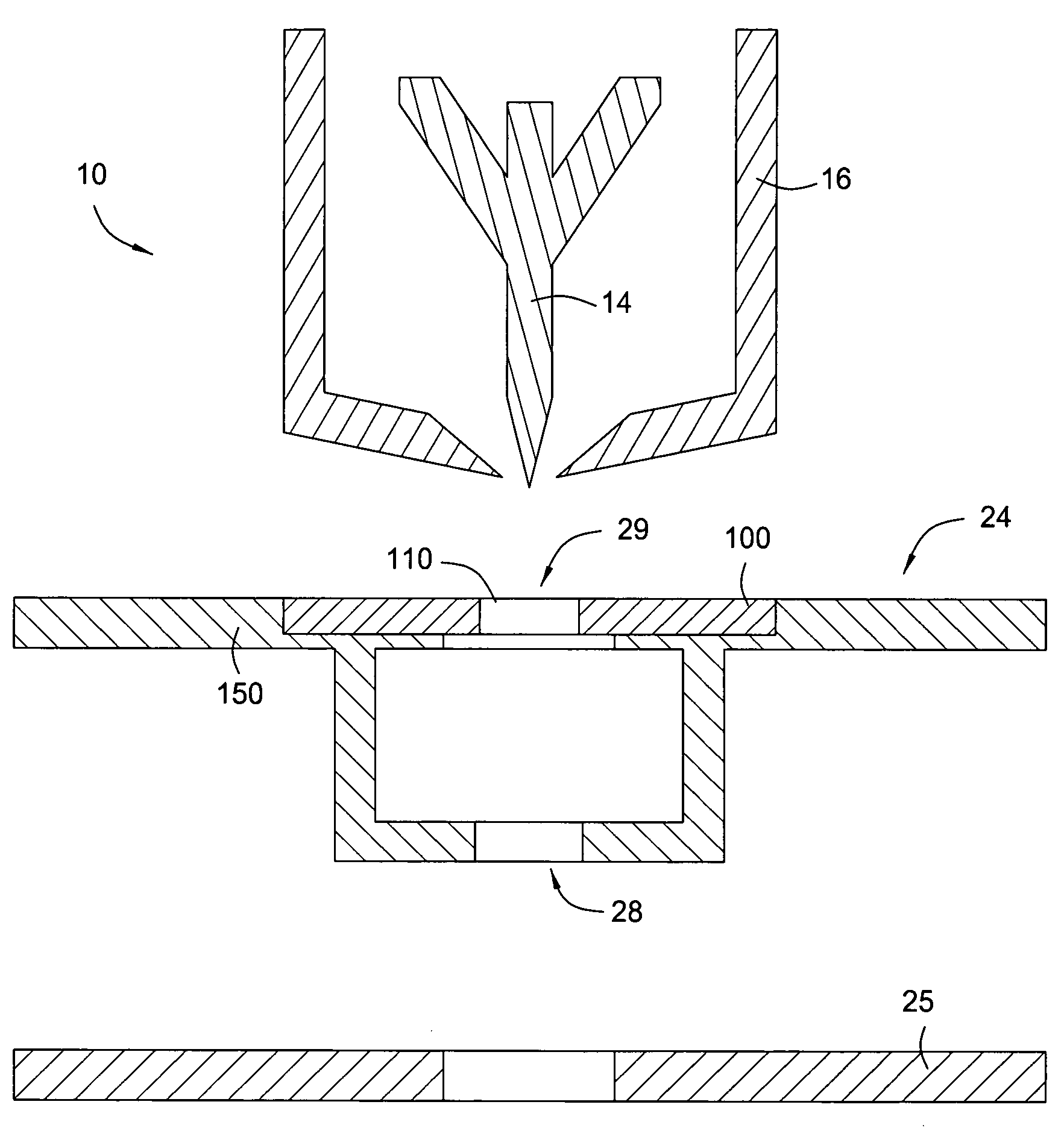
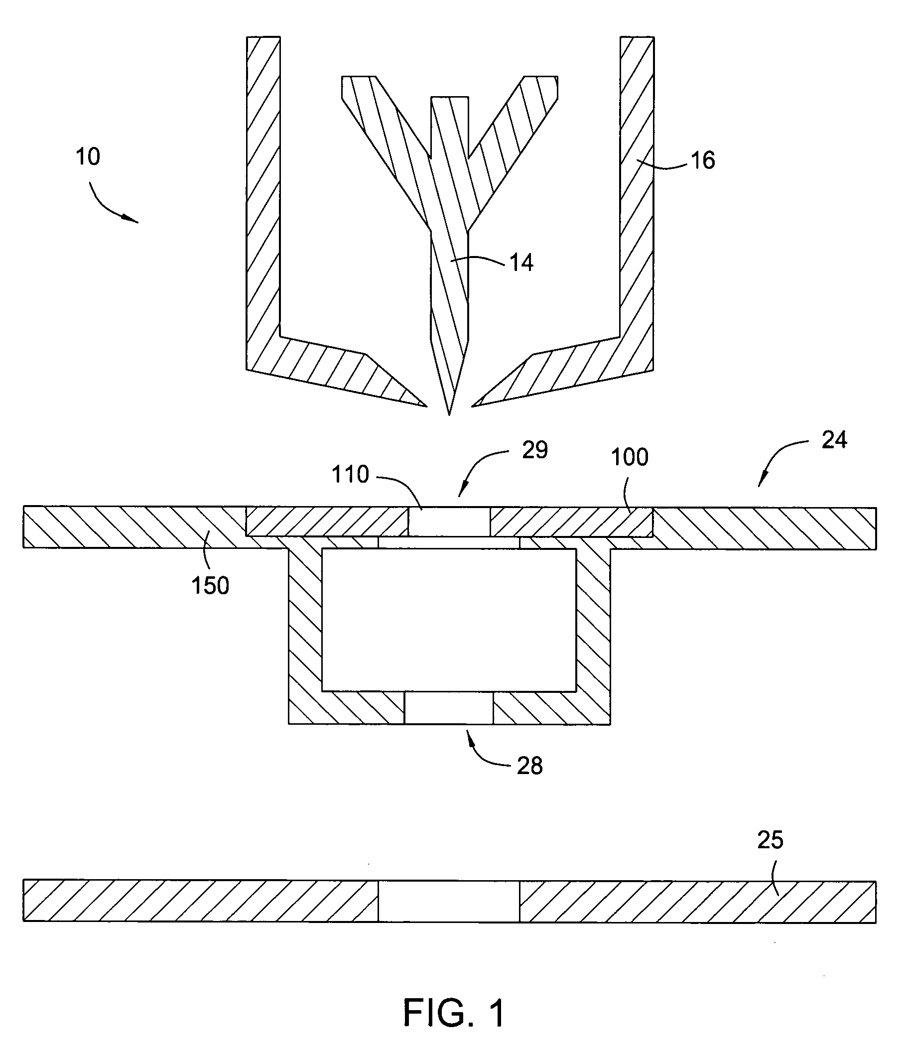
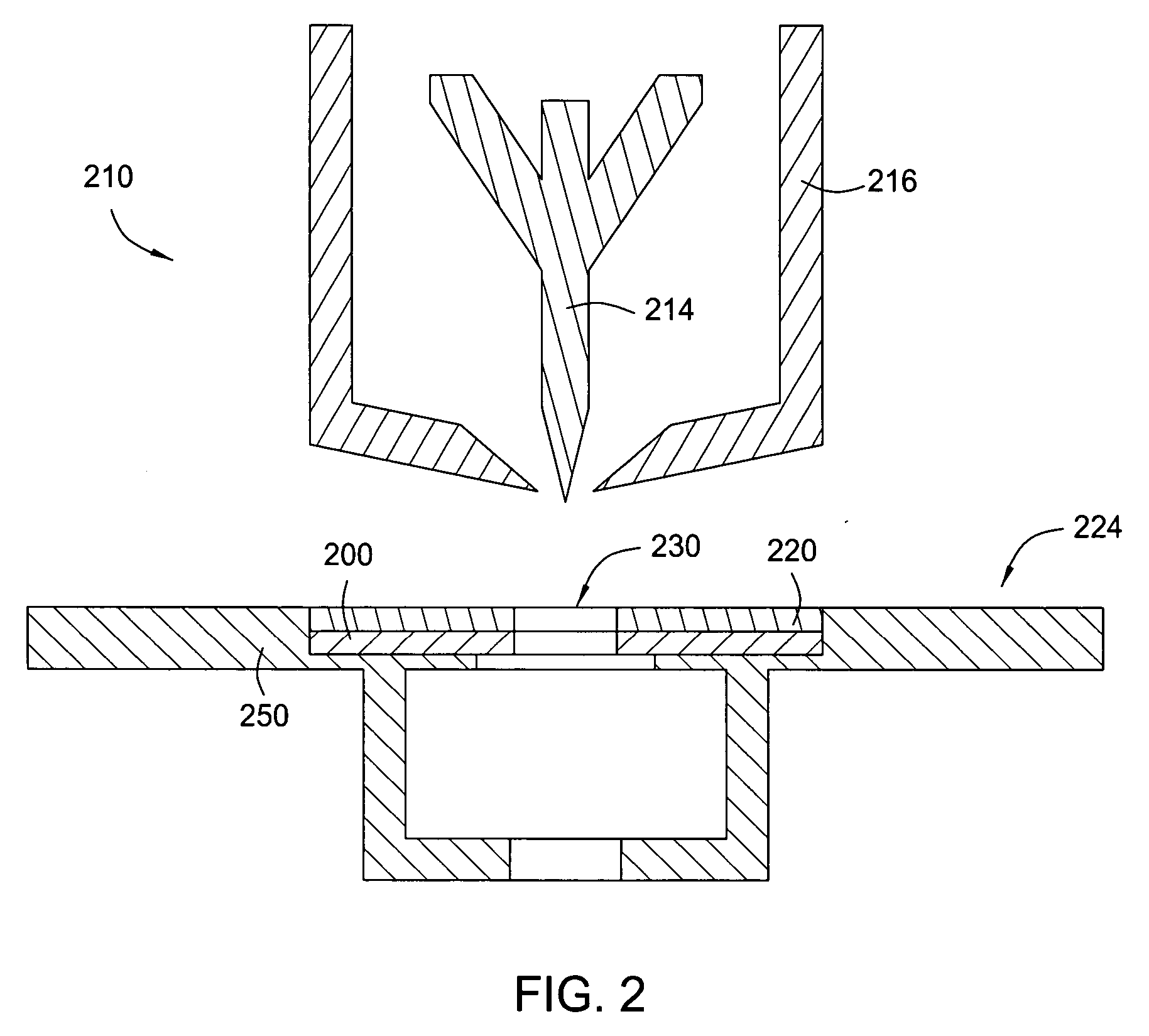
[0019]FIG. 1 illustrates a side cross sectional view of a portion of an electron gun 10 in accordance with one or more embodiments of the invention. The remainder of the electron gun 10 is not shown. The electron gun 10 may be a field emission or Schottky emission gun. Details of such a device are described in L. Swanson and G. Schwind, “A Review of The ZrO / W Schottky Cathode”, Handbook of Charged Particle Optics editor Jon Orloff, CRC Press LLC, New York, (1997), which is incorporated herein by reference. The electron gun 10 includes an emitter (cathode) 14, which is configured to generate an electron beam. The emitter 14 may be an oriented single crystal tungsten structure with a sharp point (approximately 1 micrometer radius) and mounted on a hair pin filament (not shown). The emitter 14 may be surrounded by a negatively biased suppressor electrode 16, which may be a conductive structure that prevents thermionically emitted electrons from leaving the emitter 14 anywhere but near ...


PUM


Abstract

An electron beam source for use in an electron gun. The electron beam source includes an emitter terminating in a tip. The emitter is configured to generate an electron beam. The electron beam source further includes a suppressor electrode laterally surrounding the emitter such that the tip of the emitter protrudes through the suppressor electrode and an extractor electrode disposed adjacent the tip of the emitter. The extractor electrode comprises a magnetic disk whose magnetic field is aligned with an axis of the electron beam.

Description

CROSS-REFERENCE TO RELATED APPLICATIONS [0001] This application claims benefit of U.S. provisional patent application Ser. No. 60 / 715,973, filed Sep. 10, 2005, which is herein incorporated by reference in its entirety.BACKGROUND OF THE INVENTION [0002] 1. Field of the Invention [0003] Embodiments of the present invention generally relate to electron guns (sources), and more particularly, electron guns that may be used, for instance, in electron beam lithography or electron microscopy. [0004] 2. Description of the Related Art [0005] Electron beam columns are well known for use, for instance, in electron beam lithography for imaging a pattern onto a substrate typically coated with a resist sensitive to electron beams. Subsequent development of the exposed resist defines a pattern in the resist which later can be used as a pattern for etching or other processes. Electron beam columns are also used in electron microscopy for imaging surfaces and thin samples. Conventional electron beam ...

Claims


Application Information

Patent Timeline
IPC IPC(8): H01J29/46H01J29/50
CPCH01J37/065H01J2237/06341H01J2237/06316H01J37/143H01J3/02H01J23/06H01J29/48
Inventor COYLE, STEVEN T.SCHEINFEIN, MICHAEL R.DEVORE, WILLIAM J.
Owner APPLIED MATERIALS INC
Why Eureka
Try Eureka