Systems and methods for passively shielding a magnetic field

Active Publication Date: 2007-03-15
GENERAL ELECTRIC CO
View PDF12 Cites 15 Cited by
  • Summary
  • Abstract
  • Description
  • Claims
  • Application Information

AI Technical Summary

Benefits of technology

[0005] In one aspect, a passive magnetic field shielding system for shielding a fringe magnetic field is described. The passive magnetic field shielding system includes a magnet configured to generate a uniform magnetic fiel

Problems solved by technology

Such magnetic fields are potentially dangerous and may have adverse effects on people who are within a proximity of such a magnet.
However, if a higher strength magnet, having a value of, for example, 3 T, is used, the shields may not be effective f

Method used


Image

  • Systems and methods for passively shielding a magnetic field
  • Systems and methods for passively shielding a magnetic field
  • Systems and methods for passively shielding a magnetic field

Examples


Embodiment Construction

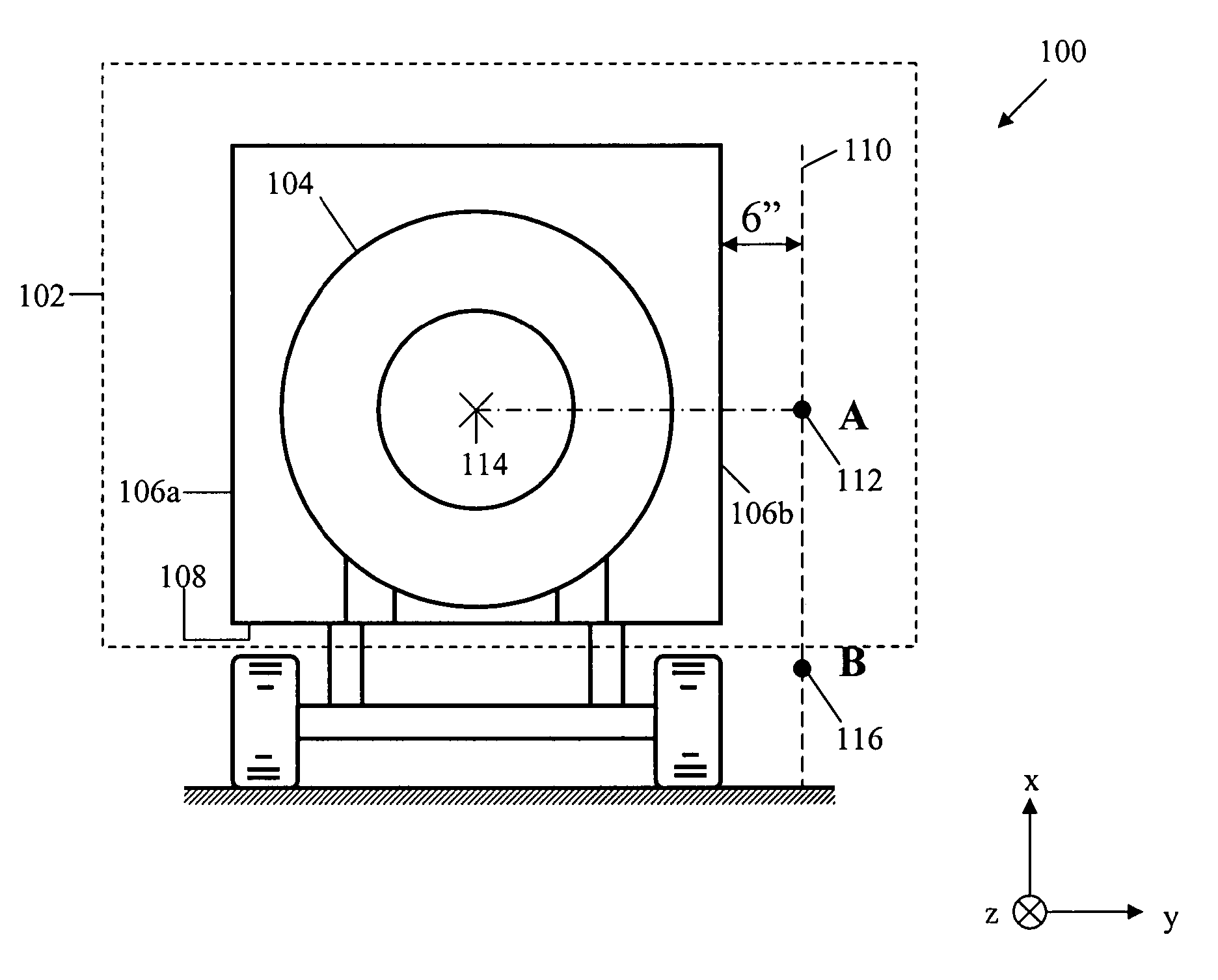
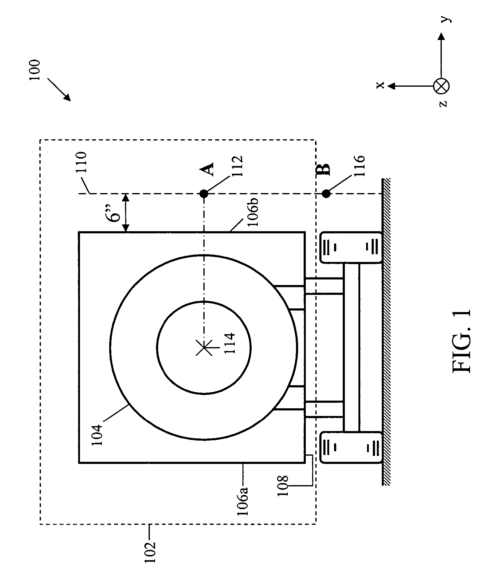
[0022]FIG. 1 shows a mobile Magnetic Resonance Imaging (MRI) Unit 100, such as a mobile van, where a passive magnetic field shielding system 102 and a magnetic field generating device, such as a magnet 104, may be used, in accordance with an exemplary embodiment of the invention. Mobile MRI unit 100 includes an imaging system such as an MRI system. Further, the MRI system may include associated electronics, such as, a computer, an operator console, a display device, an analog-to-digital converter, a sequence memory circuit, gradient coil driving circuits, a gate modulation circuit, a radio frequency power amplifier, a radio frequency oscillating circuit, a phase detector, a preamplifier, gradient coils, a transmit coil, and a receive coil as described in U.S. Pat. No. 6,529,003 B2 and used for generating magnetic resonance images. Passive magnetic field shielding system 102 further includes a side-wall 106a, a side-wall 106b, and a base 108, hereinafter collectively referred to as a...


PUM


Abstract

A passive magnetic field shielding system for shielding a fringe magnetic field is described. The passive magnetic field shielding system includes a magnet configured to generate a uniform magnetic field, an imaging system with associated electronics coupled to the magnet, and a passive shield configured to reduce the strength of the fringing magnetic field to approximately five Gauss at a distance from the passive shield.

Description

BACKGROUND OF THE INVENTION [0001] This invention relates generally to magnetic shielding and more particularly, to systems and methods for passive magnetic shielding. [0002] A magnetic field generator for Magnetic Resonance Imaging (MRI), hereinafter referred to as a magnet, having a strength of 1 Tesla (T) or higher generates a fringing magnetic fields beyond the physical dimensions of the magnet itself. [0003] Such magnetic fields are potentially dangerous and may have adverse effects on people who are within a proximity of such a magnet. As a result, it is generally considered desirable to limit or curtail the fringing magnetic fields of such magnets in an MRI system of a relocatable unit, such as a mobile van or a relocatable building. It is generally considered desirable to curtail the fringing magnetic fields below approximately five Gauss beyond a certain distance, for example, 15 centimeters, from the outside side-wall of the mobile MRI unit carrying the magnet. [0004] The ...

Claims


Application Information

Patent Timeline
IPC IPC(8): H01F7/00
CPCG01R33/421H01F27/365H01F6/00H01F27/36H01F27/366H05K9/0001A61B5/055
Inventor WANG, JIAN-SHEHUANG, JINHUAELGIN, STEPHEN R.
Owner GENERAL ELECTRIC CO
Why Eureka
Try Eureka