
Multiple-point to multiple-point communication system

Inactive Publication Date: 2007-03-15
SOCIAL FABRIC CORP
View PDF6 Cites 8 Cited by
  • Summary
  • Abstract
  • Description
  • Claims
  • Application Information

AI Technical Summary

Benefits of technology

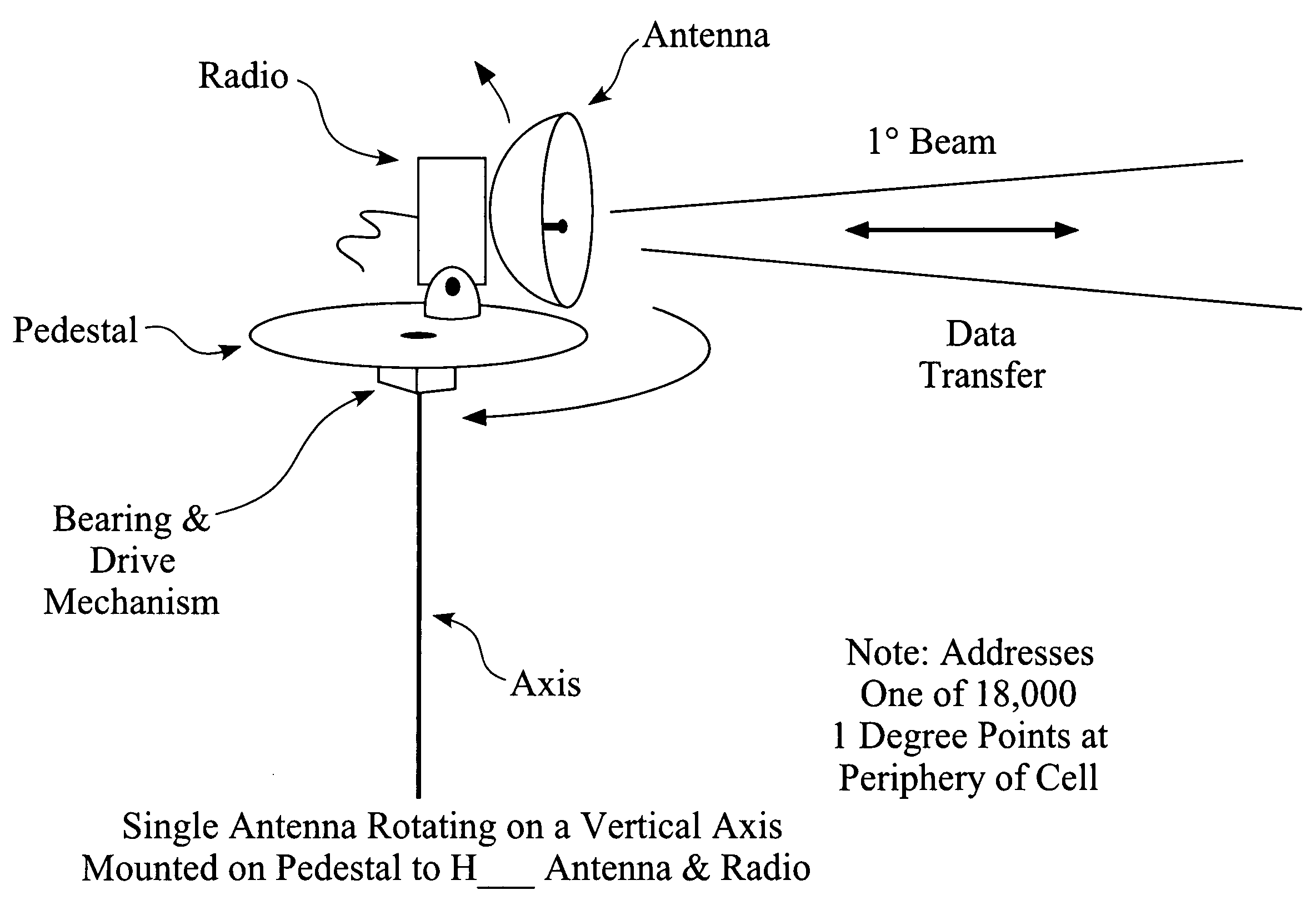
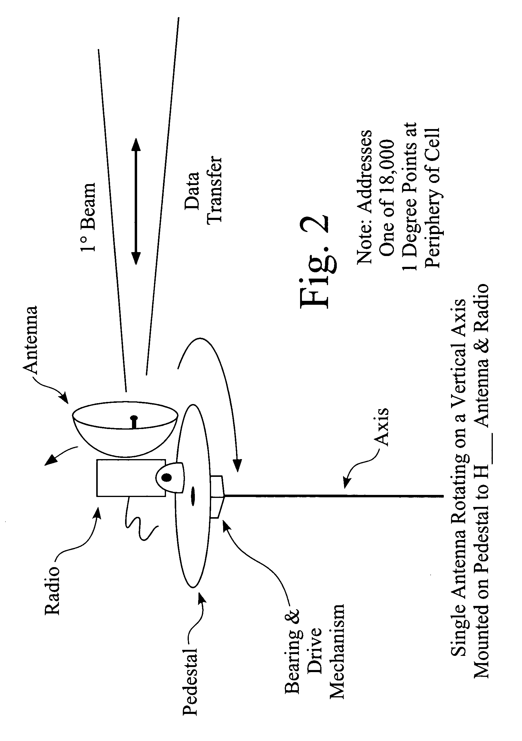
[0006] The present invention provides a high speed, wireless communication system for fixed and/or mobile terminals using a central base station antenna that produces a rotating or moving beam. In one embodiment of the invention, a antenna and a radio are mounted on top of a rotating pedestal or platform. In another embodiment, an antenna and a ra

Problems solved by technology

Providing high speed communication links for a number of fixed and / or mobile terminals can be extremely expensive.
Obtaining rights-of-way and permits to build these in-ground facilities can be costly and time consuming.
Conventional microwave links operate at relatively slow speeds, and may cause unwanted interference among the many radio receivers that are installed in and on the buildings.
The difficulty and expense of supplying broadband data links at the edges of the communication network has been described as the “Last Mile Problem.” Only about five percent of the 750,000 commercial buildings in the United States are connected by optical fibers.
Businesses that reside in the remaining ninety-five percent of commercial buildings need the high speed service offered by fiber, but are unable to obtain a fiber connection, can not afford a fiber connection, or do not have the time to wait for the installation of a fiber connection.
No current commercially-available device or system provides a readily available, relatively inexpensive high speed connection for a number of fixed and / or mobile terminals.

Method used


Image

  • Multiple-point to multiple-point communication system
  • Multiple-point to multiple-point communication system
  • Multiple-point to multiple-point communication system

Examples


Embodiment Construction

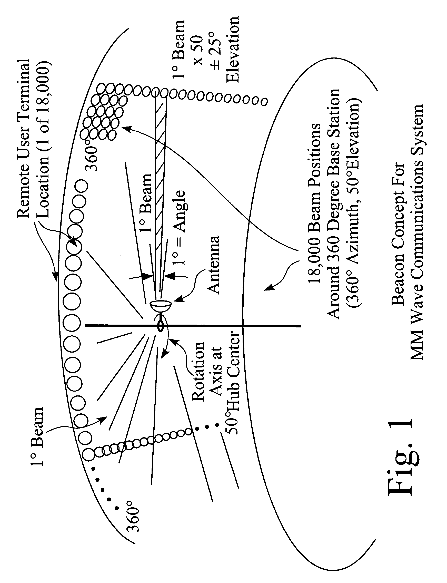
[0046]FIG. 1 depicts one particular embodiment of the invention, which comprises a central base station antenna installed on a generally vertical mast that includes a rotating beacon. In this embodiment, the antenna is generally located in the center of a cell. The antenna and a radio are mounted on the mast. The axis of rotation is aligned through the center of the radio hub.

[0047] In one embodiment of the invention, the antenna transmits and / or receives millimeter wave signals, and operates at a beamwidth of about one degree. This configuration creates approximately 18,000 beam positions around the base station (360 degrees of arc of azimuth). In this embodiment, the antenna is pointed at an elevation of fifty degrees. The elevation angle may be adjusted up or down by approximately twenty-five degrees. Consequently, this single rotating beacon can provide telecommunications services to approximately 18,000 remote user terminals.

[0048]FIG. 2 provides a detailed view of the rotati...


PUM


Abstract

Methods and apparatus for a high speed wireless communication system are disclosed. The high speed wireless links are accomplished using relatively narrow beams (<1°). These beams are produced using rotational motion at a base station in the center of a cell. In one embodiment of the invention, a radio and an antenna are mounted on a rotating element attached to a vertical mast. In another embodiment, a rotating mirror is employed to produce reflected beams. The present invention may be implemented using the 71-76 GHz, 81-86 GHz, and / or 92-95 GHz frequency bands.

Description

CROSS-REFERENCE TO A RELATED PENDING PROVISIONAL PATENT APPLICATION & CLAIMS FOR PRIORITY [0001] This Non-Provisional Patent Application is related to a Pending Provisional Patent Application, U.S. Ser. No. 60 / 707,888, filed on 12 Aug. 2005. In accordance with Sections 119 and / or 120 of Title 35 of the United States Code of Laws, the Applicants claim the benefit of priority for any subject matter which is common to the Pending Provisional and the Present Non-Provisional Patent Applications.FIELD OF THE INVENTION [0002] The present invention pertains to methods and apparatus for a high speed, wireless communication system. More particularly, one embodiment of the invention employs a rotating beam that emanates from and / or to a central base station to provide high speed wireless communications. BACKGROUND OF THE INVENTION [0003] Providing high speed communication links for a number of fixed and / or mobile terminals can be extremely expensive. Conventional links may include wire or opti...

Claims


Application Information

Patent Timeline
IPC IPC(8): H01Q3/00
CPCH01Q3/04H01Q21/20H01Q3/20H01Q3/18
Inventor LOCKIE, DOUGLAS GENESTURZA, MARK ALAN
Owner SOCIAL FABRIC CORP
Learn More