Liquid ejection head and method of manufacturing liquid ejection head

a technology of liquid ejection and manufacturing method, which is applied in the direction of resistive material coating, piezoelectric/electrostrictive transducer, transducer type, etc., can solve the problems of reducing the thickness of the adhesive layer, restricting the deformation and reducing the risk of the piezoelectric element being shorted by this ink, so as to simplify the manufacturing process

Inactive Publication Date: 2007-03-15
FUJIFILM CORP
View PDF2 Cites 9 Cited by
  • Summary
  • Abstract
  • Description
  • Claims
  • Application Information

AI Technical Summary

Benefits of technology

[0021] According to the liquid ejection head and the method of manufacturing the liquid ejection head according to the present...

Problems solved by technology

However, if the flexible printed circuit and the piezoelectric element are disposed in contact with each other, then there is a problem in that the deformation of the piezoelectric element is restricted.
Furthermore, if ink reaches the piezoelectric element, then there is a risk of the piezoelectric element being shorted by this ink.
However, in Japanese Patent Application Publication No. 6-286126, since the flexible printed circuit is actually supported by the adhesive layer, the thickness of the adhesive layer is reduced by the bonding pressure, and the flexible printed circuit makes contact with the piezoelectric elements, thereby restricting the piezoelectric elements and thus preventing stable ejection.
Furthermore, since the movable portion and the electrical connection portion of the piezoelectric element are not demarcated, then it is necessary to provide a conductive material locally on the electrode of the piezoelectric element, thus giving rise to ...

Method used


Image

  • Liquid ejection head and method of manufacturing liquid ejection head
  • Liquid ejection head and method of manufacturing liquid ejection head
  • Liquid ejection head and method of manufacturing liquid ejection head

Examples


first embodiment

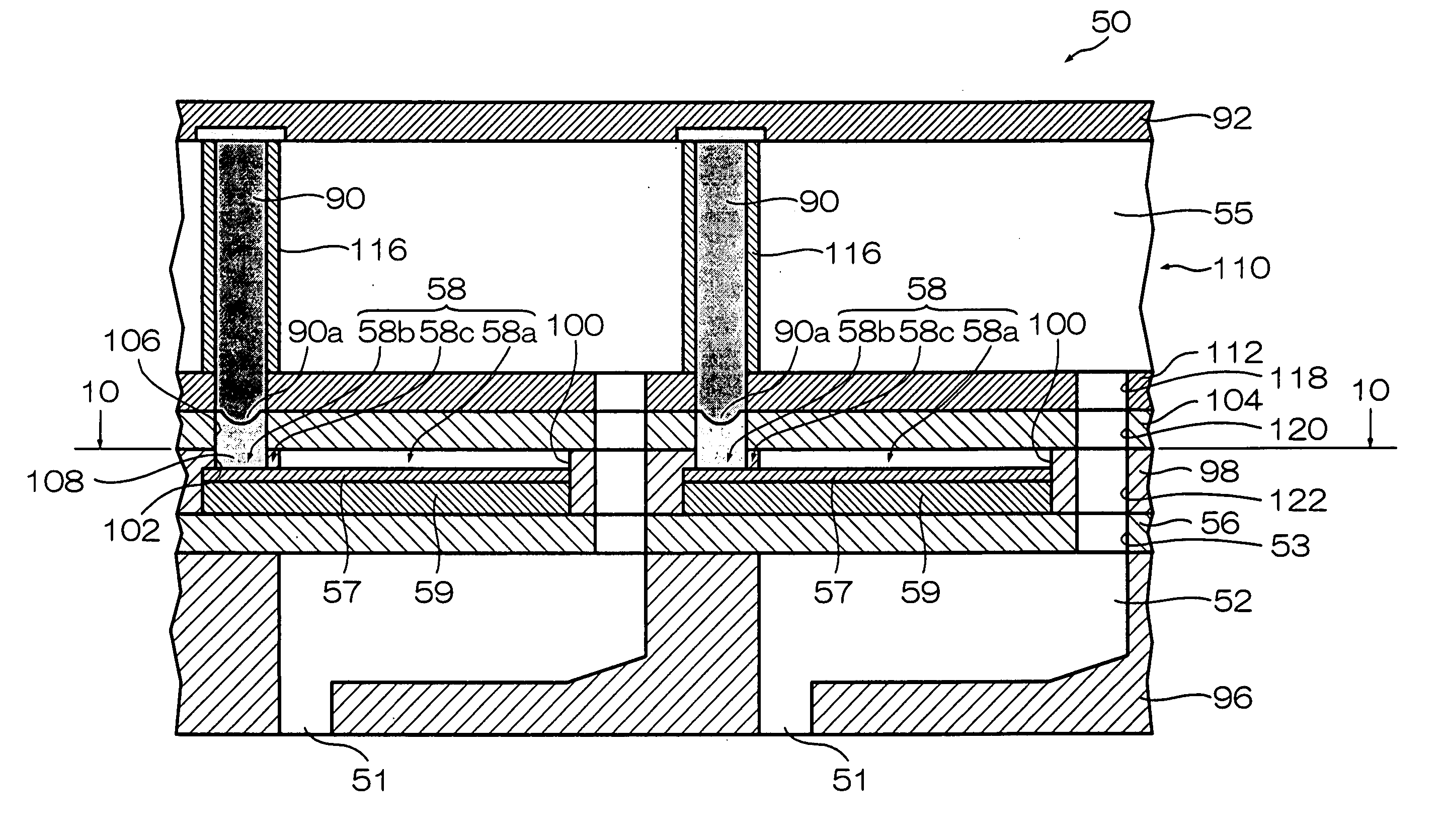
[0095]FIG. 7 is a plan view perspective diagram showing the approximate composition of the print head 50 according to a

[0096] As shown in FIG. 7, a diaphragm 56 forming the upper face of the pressure chambers 52 is disposed over the pressure chambers 52 which each comprise the nozzle 51 and the ink supply port 53. The diaphragm 56 is composed as a single plate, and piezoelectric elements 58 which individually cause the pressure chambers 52 to deform are independently positioned on the diaphragm 56.

[0097] The piezoelectric elements 58 are constituted by piezoelectric bodies 59, and an individual electrode 57 is formed on the upper surface of each piezoelectric element 58. The diaphragm 56 functions as a common electrode for the piezoelectric elements 58, and the piezoelectric elements 58 are formed by arranging the piezoelectric bodies 59 between the diaphragm 56 and the individual electrodes 57. The piezoelectric element 58 principally includes a movable portion 58a for causing the...

second embodiment

[0131] Next, a print head according to the present invention is described.

[0132]FIG. 13 is a cross-sectional diagram showing the composition of the principal part of the print head according to the second embodiment.

[0133] As shown in FIG. 13, in the print head 200 according to the second embodiment, electrical wires for applying drive voltages to the piezoelectric elements 58 are formed between the common liquid chamber 55 and the resist layer 98. These electrical wires are formed on a wiring plate 202, which is positioned between the common liquid chamber 55 and the resist layer 98.

[0134] Apart from this, the remainder of the composition is basically the same as that of the print head 50 of the first embodiment, and therefore, the same reference numerals are assigned to constituent members which are the same as the print head 50 of the first embodiment, and further description thereof is omitted here.

[0135] As shown in FIG. 13, the wiring plate 202 is bonded on the resist layer...

third embodiment

[0160] Next, a print head according to the present invention is described.

[0161]FIG. 15 is a cross-sectional diagram showing the composition of the principal part of the print head according to the third embodiment.

[0162] As shown in FIG. 15, the print head 300 according to the third embodiment has the common liquid chamber 55 formed below the piezoelectric elements 58.

[0163] The composition apart from the location of the piezoelectric elements 58 is the same as that of the print head 50 of the first embodiment, and therefore, the same reference numerals are assigned to constituent members which are the same as the print head 50 of the first embodiment, and further description thereof is omitted here.

[0164] As shown in FIG. 15, the nozzles 51, the pressure chambers 52, the ink supply ports 53 and the common liquid chamber 55 are formed in the flow channel plate 96 that is bonded to the lower surface of the diaphragm 56. The pressure chambers 52 and the common liquid chamber 55 ar...


PUM

PropertyMeasurementUnit
Electrical conductoraaaaaaaaaa

Abstract

The method manufactures a liquid ejection head comprising a pressure chamber which accommodates liquid, a diaphragm which forms a portion of the pressure chamber, a piezoelectric element which is disposed on the diaphragm and deforms the pressure chamber through the diaphragm to pressurize the liquid in the pressure chamber so as to eject the liquid from an ejection port in connection with the pressure chamber. The method comprises: a resist layer forming step of applying a resist in a liquid state onto the diaphragm on which the piezoelectric element has been disposed so as to cover the piezoelectric element, and curing the resist to form a resist layer on the diaphragm; a space forming step of separately removing the resist covering a movable portion of the piezoelectric element and the resist covering an electrical connection portion of the piezoelectric element, by exposing and developing the resist formed on the diaphragm, to separately form a movement space and a connection space for the piezoelectric element, in the resist layer; and a conductive material filling step of filling a conductive material into the connection space formed in the resist layer.

Description

BACKGROUND OF THE INVENTION [0001] 1. Field of the Invention [0002] The present invention relates to a liquid ejection head and a method of manufacturing a liquid ejection head, and more particularly, to a liquid ejection head and a method of manufacturing a liquid ejection head in which pressure chambers are deformed by means of piezoelectric elements disposed on a diaphragm, and liquid is ejected from ejection ports connected to the pressure chambers. [0003] 2. Description of the Related Art [0004] An inkjet recording apparatus is known as one apparatus for recording text characters and images onto a recording medium, such as paper. An inkjet recording apparatus forms images by means of ink dots, by causing ink to be ejected from a recording head comprising nozzles for ejecting ink, in accordance with an image signal, thereby depositing ink droplets onto a print medium, while moving the recording medium relatively with respect to the print head. Typical ink ejection methods are kn...

Claims


Application Information

Patent Timeline
IPC IPC(8): B41J2/045
CPCB41J2/14233Y10T29/49155B41J2/1623B41J2/1628B41J2/1634B41J2/1645B41J2002/14241B41J2002/14459B41J2002/14491B41J2202/18B41J2202/20B41J2202/21Y10T29/42Y10T29/49401B41J2/161
Inventor ENOMOTO, KATSUMIMAEDA, YASUHIKO
Owner FUJIFILM CORP
Why Eureka
Try Eureka