Projection system and method including spatial light modulator and compact diffractive optics

a projection system and light-modulator technology, applied in the field of spatial light-modulator display systems and methods, can solve the problems of low projection brightness levels of less than 50 lm, complex projection systems, and large space requirements for their implementation, and achieve the effect of low weight and cos

Active Publication Date: 2007-03-15
TEXAS INSTR INC
View PDF3 Cites 69 Cited by
  • Summary
  • Abstract
  • Description
  • Claims
  • Application Information

AI Technical Summary

Benefits of technology

[0018] Embodiments of the present invention solve the problem of producing a bright image in a projection system in a small physical volume with low weight and cost. Embodiments of the pr

Problems solved by technology

Recently, small LED (light-emitting diode) light sources have enabled the design of one pound, pocket-sized DLP™ projectors; however, the required optical elements generally remain as a costly contributor to the size and weight of the projector.
Since the light emitted by LEDs is typically in a Lambertian pattern with limited intensity, it has been difficult to couple LEDs into low-etendue spatial light modulator panels, resulting in low projection brightness levels of less than 50 Lm.
Such projection systems are complex and require substantial space for their implementation.
Again, this arrangement generally requires substantial volume for its construction.
Unless these elements are carefully designed, coated, and mechanically aligned, the multiple faces of the lens and prism elements can cause significant loss in contrast and light throughput.
In practice, these pr

Method used


Image

  • Projection system and method including spatial light modulator and compact diffractive optics
  • Projection system and method including spatial light modulator and compact diffractive optics
  • Projection system and method including spatial light modulator and compact diffractive optics

Examples


Embodiment Construction

[0034] The making and using of presently preferred embodiments are discussed in detail below. It should be appreciated, however, that the invention provides many applicable inventive concepts that can be embodied in a wide variety of specific contexts. The specific embodiments discussed are merely illustrative of specific ways to make and use the invention, and do not limit the scope of the invention.

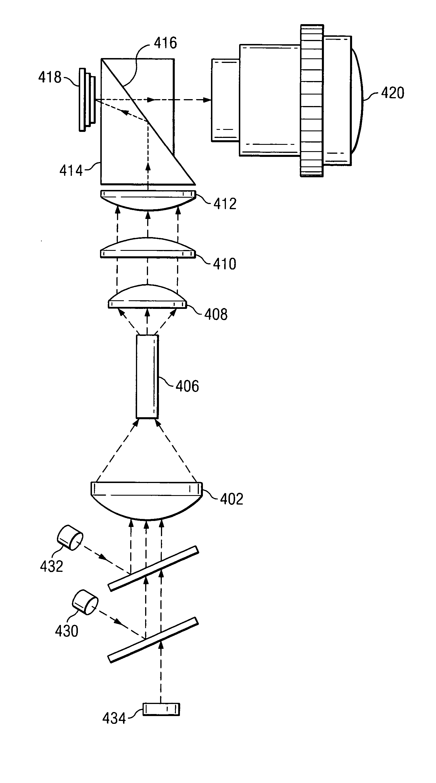
[0035] Embodiments of the invention will be described with respect to preferred embodiments in a specific context, namely an apparatus and method for projecting an image using a diffractive optical element and a spatial light modulator. Embodiments comprise an image projection system using a holographic optical element, a spatial light modulator, and solid-state light sources that advantageously can be configured in a small volume. Alternative embodiments further comprise a second holographic optical element to redirect waste light to improve projected image quality.

[0036] An illumina...


PUM


Abstract

A method and apparatus for a projection display system includes a spatial light modulator and a volume illumination hologram. The spatial light modulator comprises a digital micromirror device, and the projection system includes a laser light source to produce a sequence of collimated, colored, light beams for the illumination hologram. Waste light produced by the spatial light modulator is transmitted to the illumination hologram, and the illumination hologram emits waste light from at least one of its edges. Waste light emitted from an edge of the illumination hologram is absorbed by a light sensor to control the intensity of the light beams. A projection focusing element is mounted proximate a side of the illumination hologram to focus the image beam from the spatial light modulator for viewing. A projection hologram is interposed between the side of the illumination hologram and the projection focusing element to manage waste light.

Description

TECHNICAL FIELD [0001] This invention relates generally to the field of spatial light modulator display systems and methods, and more particularly to spatial light modulator display systems and methods including a holographic optical element. BACKGROUND [0002] Spatial light modulators, such as a DMD (digital micromirror device), can be used to create projectable images that are displayed in rear-projection television receivers and in consumer, business, and large-venue image projection systems. Other spatial light modulators such as LCDs (liquid crystal displays) are also used in some image projection applications. An example of a digital micromirror device is a DLP™ (“digital light processor”), manufactured by Texas Instruments, which uses an array of micromirrors with selectively controllable orientations to form a projectable image. Digital micromirror devices generally are the preferred image-forming components in projection systems requiring high illumination levels. As an exam...

Claims


Application Information

Patent Timeline
IPC IPC(8): G03B21/20
CPCG03B21/2033H04N5/7416H04N9/3197H04N9/3117H04N9/315H04N9/3114
Inventor PENN, STEVEN MONROEDEWALD, DUANE SCOTTBARRY, RONALD ALLEN
Owner TEXAS INSTR INC
Why Eureka
Try Eureka