Optical scanner and image forming apparatus

an image forming apparatus and optical scanner technology, applied in the field of optical scanners and image forming apparatuses, can solve the problems of increasing the number of components, reducing the productivity of the apparatus, and requiring more light sources for tandem type image forming apparatuses, so as to reduce the number of light sources, reduce color irregularities and color shifts without adversely affecting the image, and speed up the effect of speed

Inactive Publication Date: 2007-03-15
RICOH KK
View PDF12 Cites 121 Cited by
  • Summary
  • Abstract
  • Description
  • Claims
  • Application Information

AI Technical Summary

Benefits of technology

[0027] According to one embodiment of the present invention, an optical scanner and an image forming apparatus including the same can output images at high speed, and appropriately reduce color irregularities and color shifts without adversely affecting the images, even with a reduced number of light sources. Further, as the number of light sources can be reduced, the overall failure rate of the unit can be reduced, so that a long service life can be achieved. Moreover, a light beam e

Problems solved by technology

However, these apparatuses have a disadvantage in terms of productivity.
However, a tandem type image forming apparatus requires more light sources.
Accordingly, the number of components increases, color shifts are caused by differences in wavelengths among the plurality of light sources, and the cost increases.
Further, deterioration of semiconductor lasers cause failures i

Method used


Image

  • Optical scanner and image forming apparatus
  • Optical scanner and image forming apparatus
  • Optical scanner and image forming apparatus

Examples


first embodiment

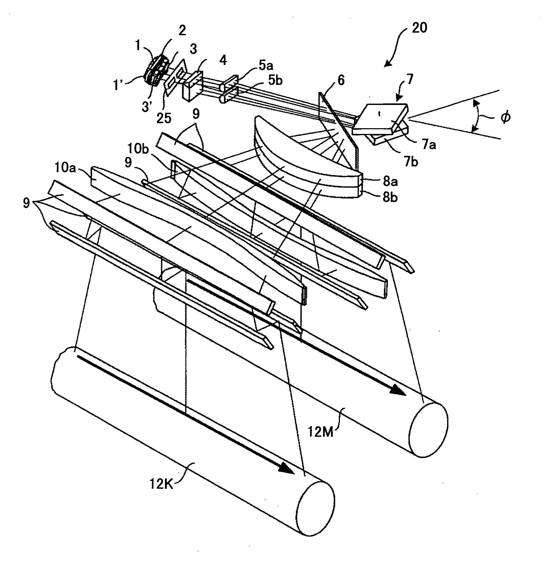
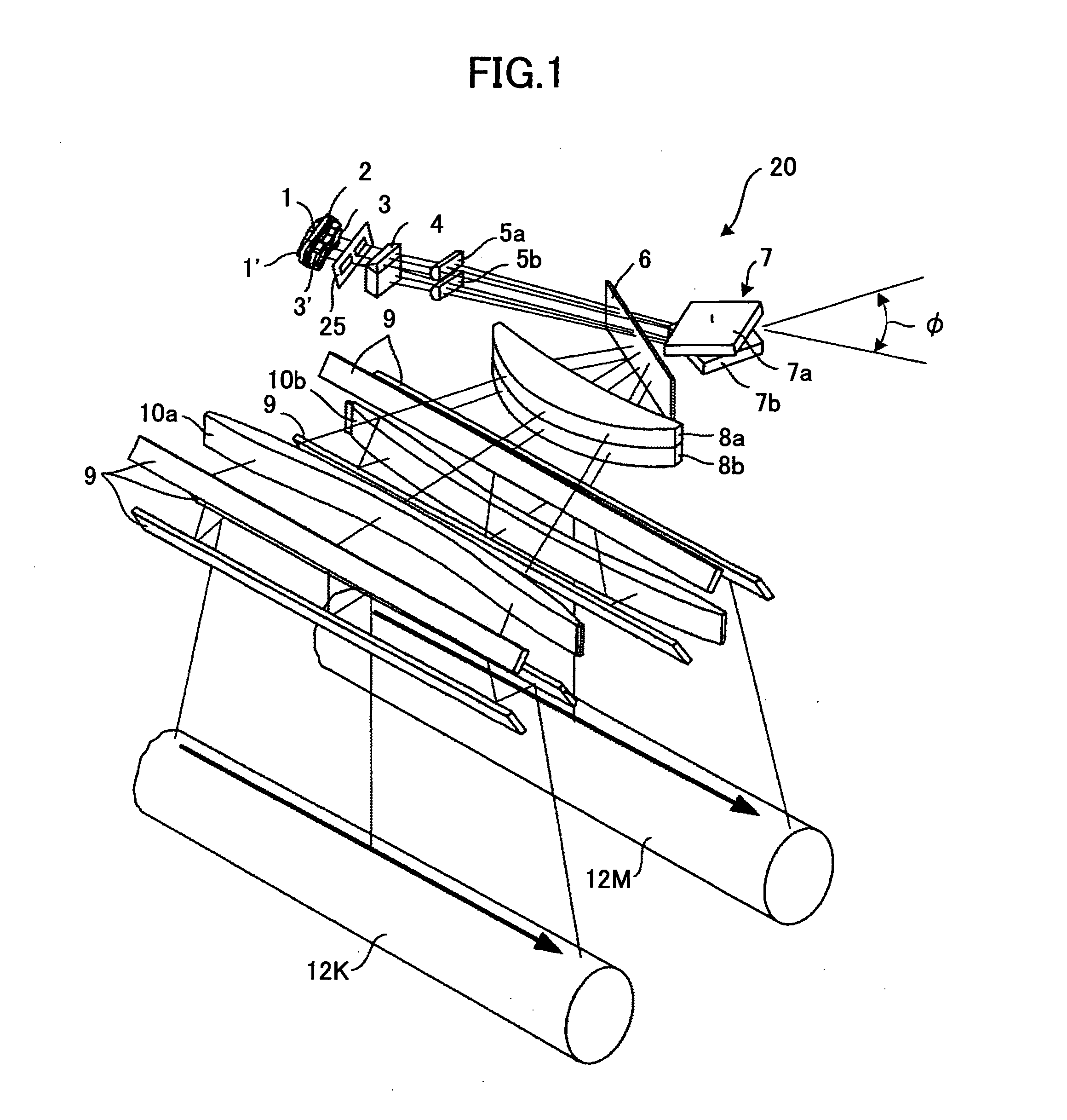
[0055]FIG. 1 is a partially omitted perspective view of an optical scanner 20 according to the present invention.

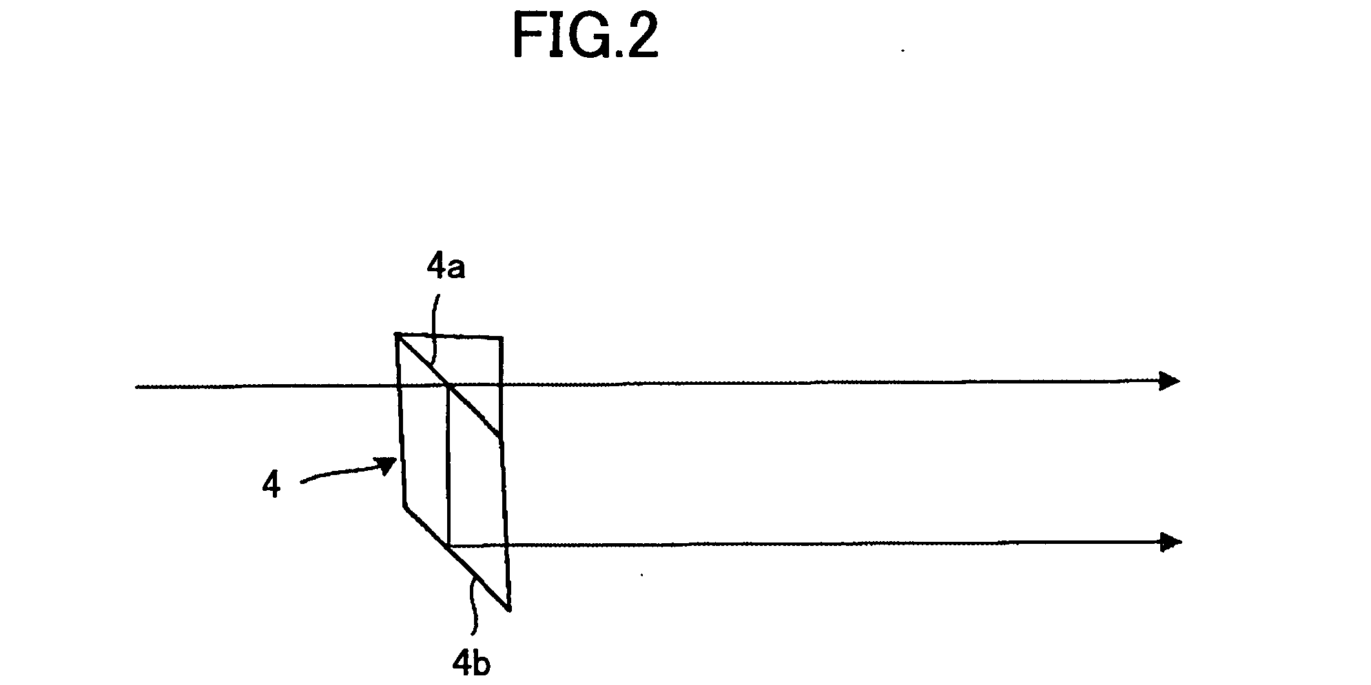
[0056] First, a summary of the configuration and functions of the optical scanner 20 according to the first embodiment is described with reference to FIG. 1. In FIG. 1, reference numerals 1, 1′ denote semiconductor lasers functioning as light sources, 2 denotes a support base (LD base) of the semiconductor lasers, 3, 3′ denote coupling lenses, 4 denotes a half mirror prism functioning as a light flux dividing unit, 5a, 5b denote cylindrical lenses, 6 denotes a noise insulating glass, 7 denotes a deflecting unit including an upper polygon mirror 7a and a lower polygon mirror 7b functioning as reflection polygon mirrors, 8a, 8b denote first scanning lenses of an optical scanning system, 9 denotes mirrors in the optical scanning system, 10a, 10b denote second scanning lenses in the optical scanning system, 12K, 12M denote photoconductors that are subject to scanning, and 25 ...

third embodiment

[0191] A third embodiment according to the present invention is described with reference to FIG. 7 and FIG. 10.

[0192] The write start timing of an image is described in the present embodiment. When scanning a surface with an optical scanner, the write start timing of an image is determined on the basis of a light detection timing detected by a light detecting unit such as a photodiode provided at the starting side of optical scanning and outside the image forming area. Specifically, the write start timing is the timing of starting to write an image at a starting point of the image forming area after a light is detected by the light detecting unit.

[0193] Even if the write start timing is the same for different surfaces, the light beams pass through different optical systems before reaching the surfaces to be scanned. As a result, the surfaces have different write start positions, which may lead to color shifts in the resultant image. To compensate for the differences, it is necessar...

fourth embodiment

[0198] A fourth embodiment according to the present invention is described with reference to FIG. 7 and FIG. 11.

[0199] The clock frequency is described in the present embodiment. As described above, even if the same clock frequency is used for scanning a plurality of different surfaces, optical elements (scanning lens, optical path bending mirror, etc.) through which a light beam passes before reaching the surfaces are different among the surfaces. Therefore, images created on the different surfaces will have different total widths.

[0200] Moreover, the temperatures of scanning lenses (made of plastic) may differ in the environment where the image forming apparatus is used, and therefore, the scanning lenses may have different expansion coefficients. Accordingly, images created on the different surfaces will have different total widths.

[0201] The total width of an image can be corrected by changing the clock frequency of the light source. By switching the clock frequency of the lig...


PUM


Abstract

An optical scanner includes a light source; a deflecting unit that deflects and scans a light beam emitted from the light source; a scanning optical system that focuses the light beam deflected and scanned onto different surfaces to be scanned; and a light quantity correcting unit that corrects a light quantity of the light beam. The light quantity correcting unit changes light quantity correction data used for correcting the light quantity of the light beam for each of the surfaces. The light quantity correction data is dependent on positions in a main scanning direction.

Description

BACKGROUND OF THE INVENTION [0001] 1. Field of the Invention [0002] The present invention relates to an optical scanner and an image forming apparatus such as a copier, a printer, a facsimile machine, and a plotter including the same. [0003] 2. Description of the Related Art [0004] Electrophotographic image forming apparatuses such as laser printers, digital copiers, and plain paper facsimile machines for creating color documents at high speed are becoming increasingly widespread, and tandem type image forming apparatuses including a plurality of (typically four) photoconductors are becoming popular. [0005] There are color electrophotographic image forming apparatuses that only include one photoconductor, which is rotated corresponding to the number of colors. However, these apparatuses have a disadvantage in terms of productivity. Specifically, if there are four colors and only one photoconductive drum, the photoconductor needs to be rotated four times. [0006] However, a tandem typ...

Claims


Application Information

Patent Timeline
IPC IPC(8): G02B5/18
CPCG02B26/127G02B26/123
Inventor IMAI, SHIGEAKINAKAJIMA, TOMOHIROHAYASHI, YOSHINORI
Owner RICOH KK
Why Eureka
Try Eureka