Low jitter clock recovery circuit

a recovery circuit and low jitter clock technology, applied in the direction of oscillation comparator circuits, digital transmission, pulse automatic control, etc., can solve the problems of data loss or misinterpretation

Active Publication Date: 2007-03-15
RAMBUS INC
View PDF20 Cites 60 Cited by
  • Summary
  • Abstract
  • Description
  • Claims
  • Application Information

AI Technical Summary

Problems solved by technology

If the clock used by the receiving device is out of synchronization wit

Method used


Image

  • Low jitter clock recovery circuit
  • Low jitter clock recovery circuit
  • Low jitter clock recovery circuit

Examples


Embodiment Construction

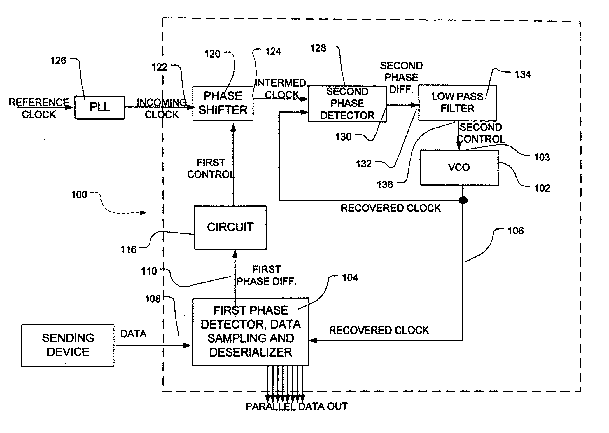
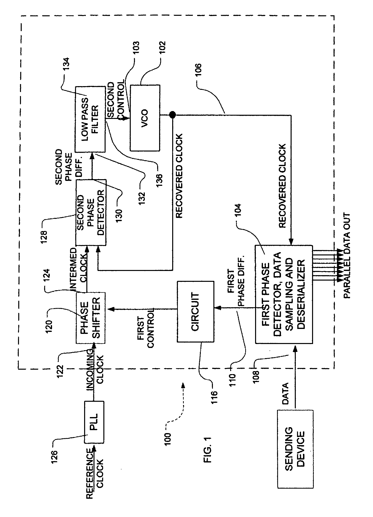
[0013] A clock recovery circuit 100 according to one embodiment of the invention (FIG. 1) incorporates a clock source 102 which, in this embodiment, is a voltage-controlled oscillator or “VCO.” VCO 102 is arranged to generate a clock signal referred to herein as a “recovered clock signal”, also referred to herein as a “first clock signal.” The recovered clock signal may be a single-component system or may include a plurality of components in a predetermined phase relationship with one another as, for example, an in-phase or I component; a Q component in quadrature with the I component; and the compliments I and Q of these components. The VCO may be, for example, a ring oscillator or an oscillator with inductive and capacitive components, commonly referred to as an LC oscillator.

[0014] The clock recovery system 100 also includes a first phase detector which, in this embodiment, is integrated with a data sampling device and a deserializer in a unit 104. The first phase detector is ...


PUM


Abstract

A clock recovery circuit includes a first phase detector for measuring the phase difference between a first clock signal from a voltage controlled oscillator (VCO) and a data signal. A phase shifter responsive to a control signal based on this phase difference adjusts the phase of an incoming clock signal to yield a second clock signal. The phase difference between the first clock signal and the second clock signal is measured and the resulting signal is low-pass filtered to derive a control signal for controlling the VCO. The phase locked loop including the VCO filters out jitter.

Description

BACKGROUND OF THE INVENTION [0001] Digital devices as, for example, circuits within a computer, send information to one another by varying a parameter of a signal as, for example, an electrical voltage, during successive intervals set by a clock in the sending device. In a binary system, the sending device sets the signal parameter for each interval either to a first value to denote a 1 or a second value to denote a 0 during each interval. The receiving device takes successive samples of the signal at times corresponding to the intervals in the signal and determines, for each such sample, whether the parameter denotes a “0” or a “1.” To do this, the receiving device must have a clock signal synchronized with the intervals in the incoming data signal. If the clock used by the receiving device is out of synchronization with the intervals of the data signal, data can be lost or misinterpreted. To communicate data at high speed, it is desirable to make the bit intervals as short as poss...

Claims


Application Information

Patent Timeline
IPC IPC(8): H03D3/24
CPCH03D13/004H03L7/07H03L7/081H04L7/0331H03L7/0891H03L7/091H04L7/033H03L7/087
Inventor WERNER, CARL WILLIAM
Owner RAMBUS INC
Why Eureka
Try Eureka