Retrieval catheter

a technology of stenting catheter and stent, which is applied in the field of stenting catheter, can solve the problems of all the protections against debris escape during stenting procedure, and the effect of low bending resistance and good pushability

Active Publication Date: 2007-03-15
CR BARD INC
View PDF10 Cites 15 Cited by
  • Summary
  • Abstract
  • Description
  • Claims
  • Application Information

AI Technical Summary

Benefits of technology

[0022] Much of the engineering of the distender and the pusher can be “borrowed” from the teaching which the present Applicant has made available in above mentioned WO 01 / 34061. For US purposes, it is hereby stated that all of the disclosure of WO 01 / 34061 is hereby incorporated in the present patent application by this reference to it. Specifically, for the pusher one envisages a stainless steel hypotube or other system which is of small cross-sectional dimensions but nevertheless exhibits high resistance to buckling (good pushability) together with low resistance to bending, so that the retrieval catheter system can be advanced along tortuous bodily lumens. The skilled reader will appreciate that the objectives of pushability and trackability are nothing new for the present retrieval catheter but are requirements of most transluminal percutaneous catheter systems.

Problems solved by technology

Clearly, all the protections against escape of debris during the stenting procedure counts for nothing if withdrawal of the protection device itself releases debris which remains uncaptured.
In particular, a retrieval catheter with an atraumatic distal tip that tapers to a point is hardly adapted to create, in combination with the device to be retrieved, a system devoid of any discontinuities or surfaces that might snare, snag or scrape any surface of the stent through which the system is to be proximally withdrawn.

Method used


Image

  • Retrieval catheter
  • Retrieval catheter
  • Retrieval catheter

Examples


Embodiment Construction

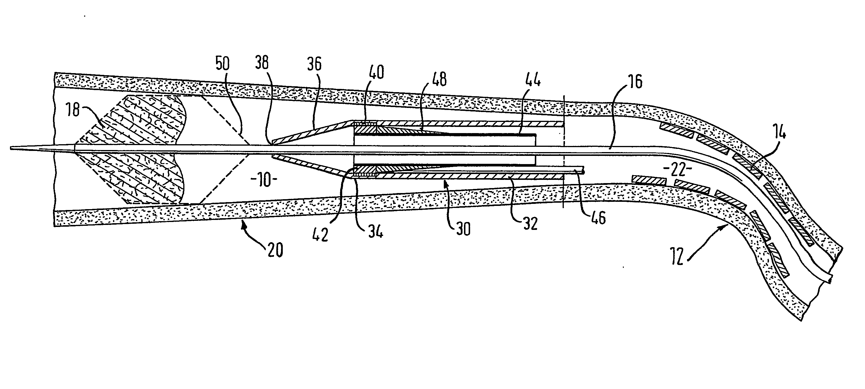
[0030] Referring first to FIG. 1, within the carotid artery 10 of a human body, at a constricted portion 12 of the lumen, has been placed a stent 14. On a guidewire 16 which extends through the stent lumen is provided an embolic filter device 18 at the distal tip of the guidewire. This filter occludes the lumen 10 at a portion 20 which is distal of the stent 14 relative to the point of entry of the guidewire 16 into the body. As can be seen, the filter device 18 occludes the lumen 10 in the zone 20.

[0031] The stent 14 having been successfully placed in the lumen 10, it becomes necessary to remove the filter protection device 18 through the relatively narrow lumen 22 of the stent. It can be appreciated that there is a substantial risk that some part of the filter device 18 will snag on some part of the matrix of the stent 14, or else of some portion of bodily tissue protruding through the interstices of the expanded stent 14 matrix into the stent lumen 22.

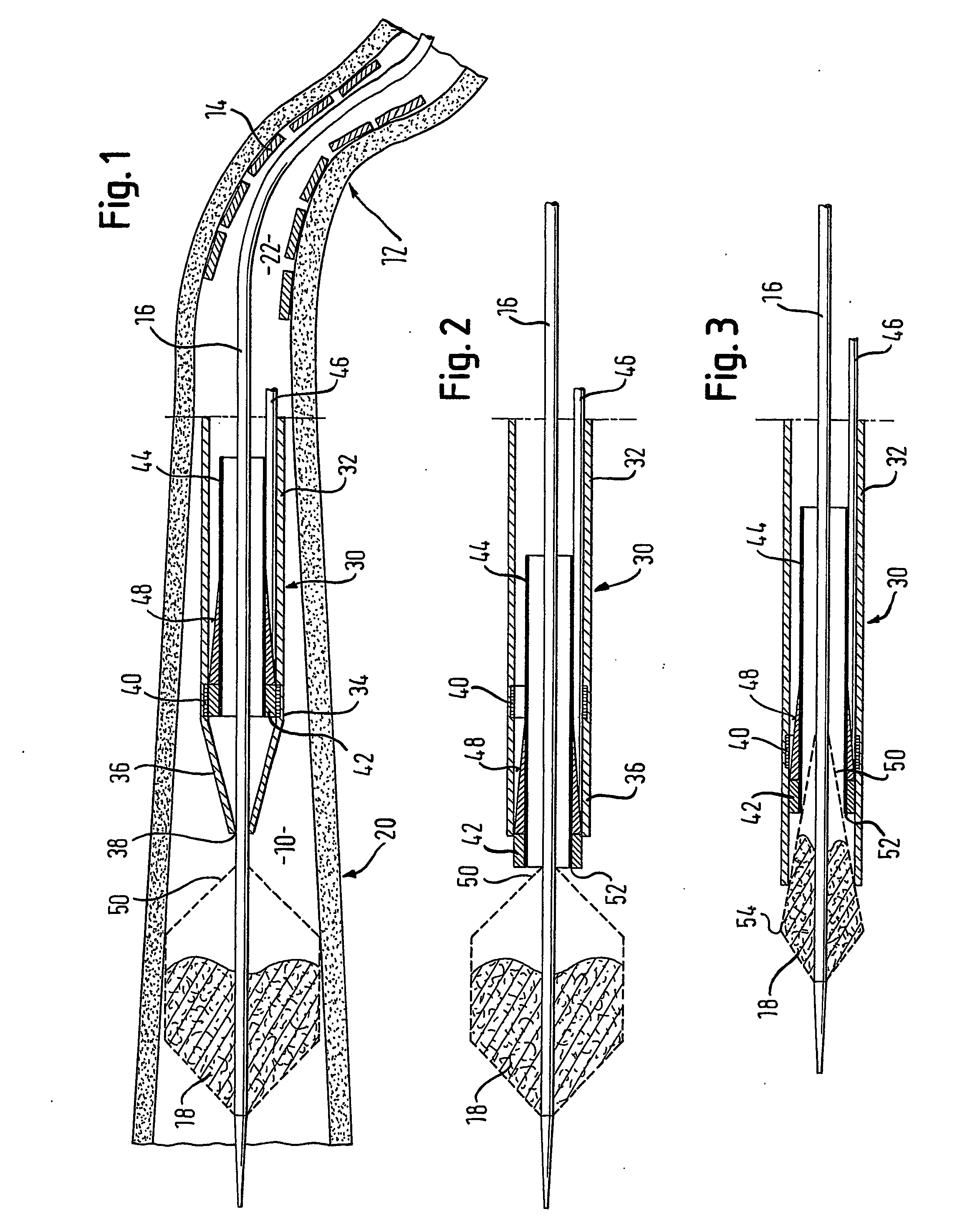
[0032]FIG. 1 shows a retri...


PUM


Abstract

A retrieval catheter (30) for retrieving from a bodily lumen a device (48) attached to the distal end of a pull line (16), the catheter having a wall (32) that defines a catheter lumen (22) and a distal tip (36) that is tapered towards an open distal orifice (38) that defines the distal end of the lumen, the wall over the length of said tapered tip being distensible to allow the orifice to expand, the catheter having: a distender within the lumen that can be urged distally along the lumen such that the distender presses radially outwardly the catheter wall within the distal tip, so as to distend said orifice; the distender having a distal end annulus and a proximal end annulus (42) separated by a radially outward-facing circumferential wall and an axial lumen extending through the distender between said distal and proximal annuli; a pusher shaft (46) that extends from the distender proximally along the catheter lumen to proximally beyond the proximal end of the catheter lumen and that is arranged to push the distender distally until the distal end annulus is distal of the catheter distal orifice and the open distal orifice of the catheter is distended; whereby, with said pull line extending from the device to be retrieved through the lumen of the distender and the lumen of the catheter, the device can be pulled proximally by the pull line relative to the catheter until at least the most proximal part of the device slides over the distal end annulus of the distender into the lumen of the distender.

Description

FIELD OF THE INVENTION [0001] This invention relates to a retrieval catheter. BACKGROUND [0002] A retrieval catheter is disclosed in WO-A-01 / 12082. The catheter can be used to retrieve an embolic filter from the vasculature. It features an elongate flexible tube which has a radially expansible distal tip with an open mouth for retrieval of the filter. A centering catheter is used to centralize the retrieval catheter within the vasculature. This enables the retrieval catheter to pass freely through a stenosis or a stent to retrieve a filter. [0003] The present Applicant has disclosed in WO-A-01 / 34061 a catheter device for delivering an implant, particularly a self-expanding stent. The catheter has an atraumatic distal tapered tip and a lumen just proximal of the tapered tip in which a self-expanding stent is carried. Just proximal of the stent so carried is a pusher ring which abuts the proximal end of the compressed stent within the lumen. For delivery of the stent, the pusher is he...

Claims


Application Information

Patent Timeline
Patent Type & Authority Applications(United States)
IPC IPC(8): A61M29/00A61F2/01A61F2/95
CPCA61F2/95A61F2002/9528A61F2002/011A61F2/011
Inventor DORN, JURGENSUPPER, WOLFGANGWUBBELING, MARTIN
Owner CR BARD INC
Why Eureka
Try Eureka