Modular pole tent and joining means

Active Publication Date: 2007-03-22
TENTNOLOGY
View PDF27 Cites 19 Cited by
  • Summary
  • Abstract
  • Description
  • Claims
  • Application Information

AI Technical Summary

Benefits of technology

[0017] The novel keder rail and the “prayer” cover flaps of the present invention additionally provide a water tight interface between adjacent membrane modules. This makes it possible to join the tent modules in the valleys, or low points of the membrane, rather than at the pole tops and ridges as in the prior art (i.e. where field joints are limited to relative high regions of the membrane). By joining tent modules at the pole tops and ridges, the cost of manufactu

Problems solved by technology

Modularization of the membrane presents challenges for joining it into one weather-proof membrane.
Field joints are generally labour intensive, prone to leaking, and often unsightly.
Fabric joints on frame tents are made at the beams and are often prone to leaking water.
However, such beams are not used in a pole supported tent, necessitating beam-free joints.
However, their use is limited becaus

Method used


Image

  • Modular pole tent and joining means
  • Modular pole tent and joining means
  • Modular pole tent and joining means

Examples


Embodiment Construction

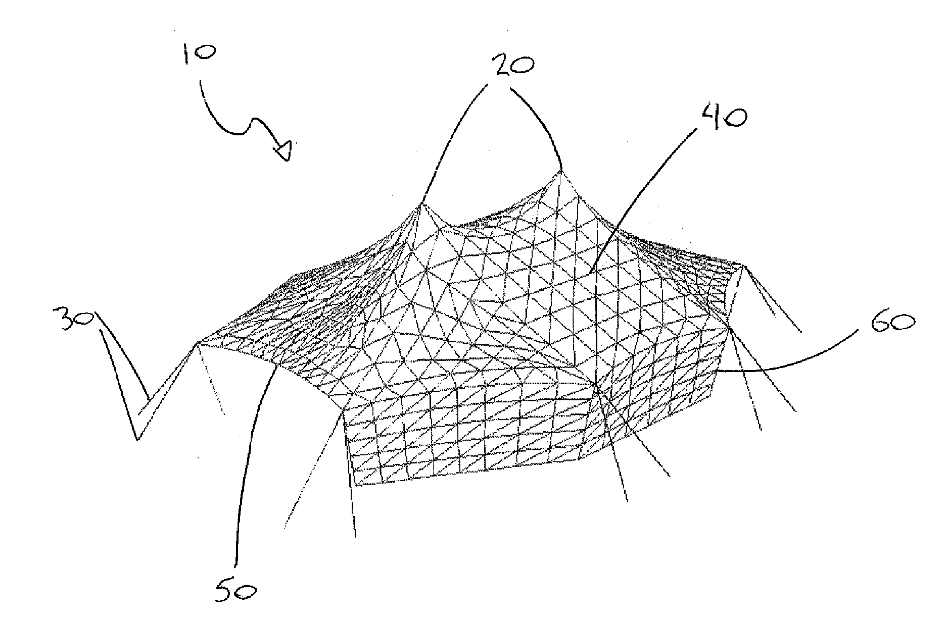
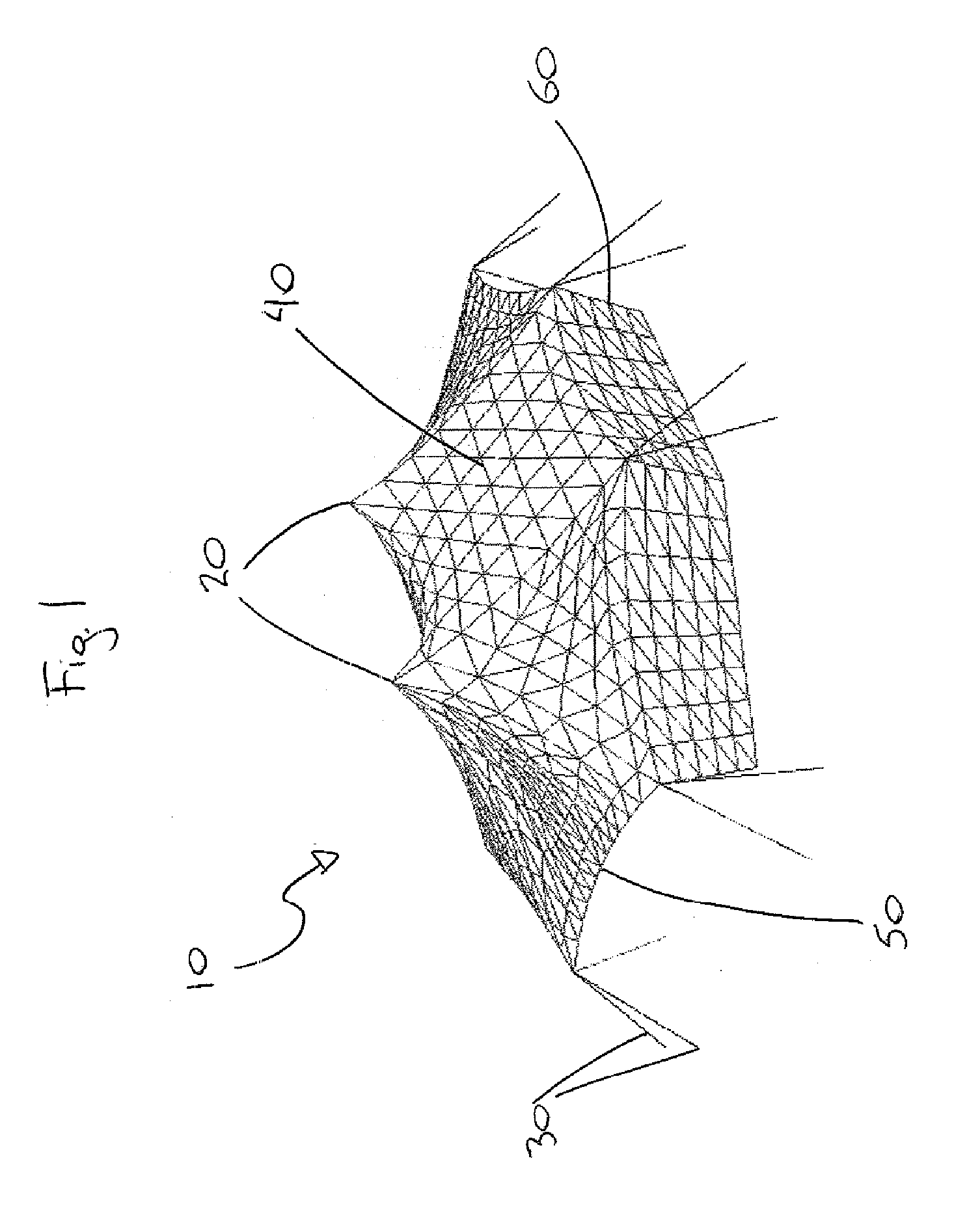
[0037] Referring to FIG. 1, a pole tent 10 is shown, having peaks 20 and anchor lines 30. The flexible membrane 40 of the tent has perimeter catenaries 50. Tent wall 60 may be removed and / or repositioned to another side of the tent 10 (see, for example, FIGS. 2(a) and 2(b)).

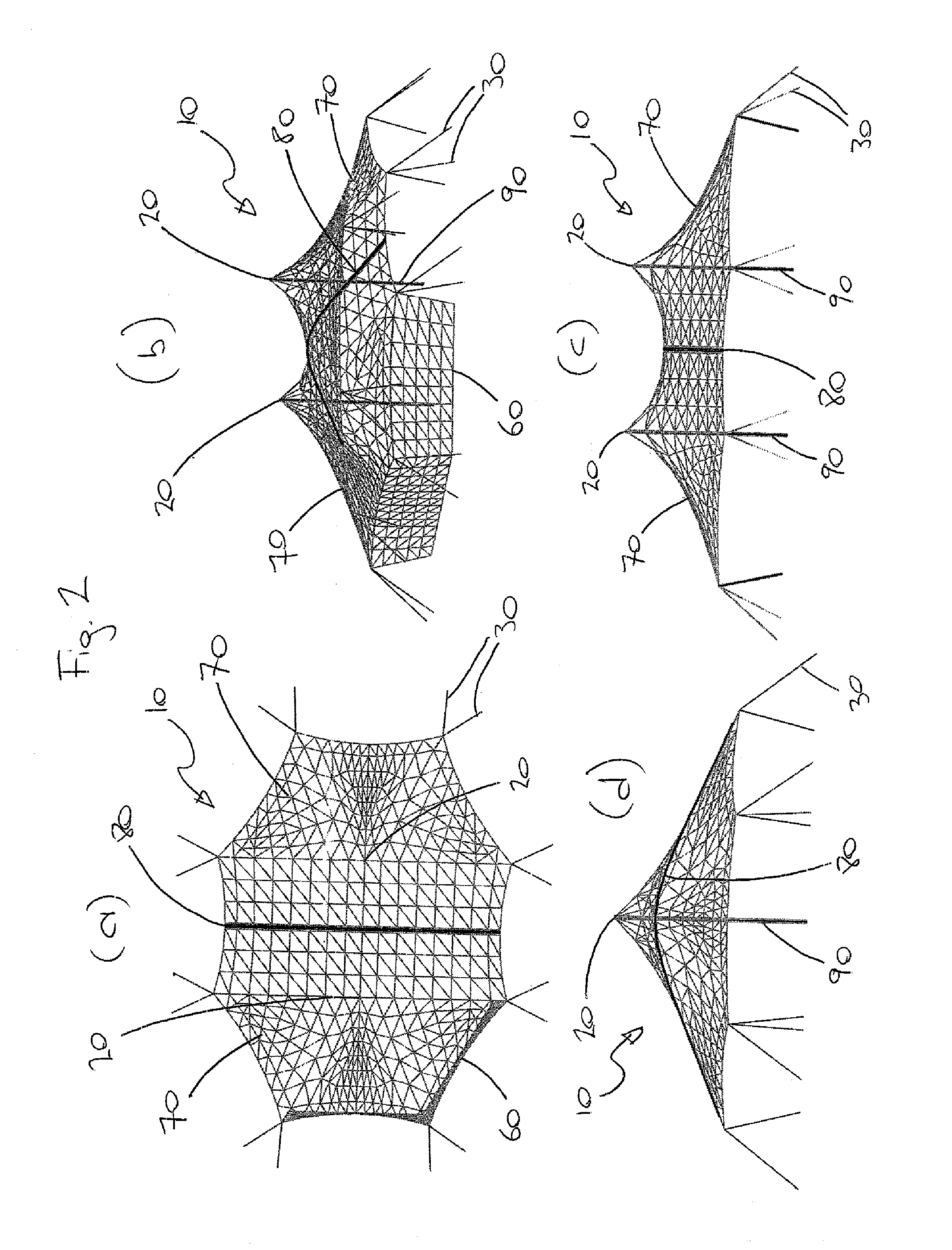
[0038] Referring to FIGS. 2(a-d) and 12, the membrane 40 of the tent 10 is made up of two modules, or bays, 70. The modules 70 are joined to one another along an interface or field joint 80, the details of which will be described more fully below. The interface 80 passes through a valley, (i.e. low point) of the membrane 40. The tent 10 has two centre poles 90, each supporting a respective one of the peaks 20, and eight corner posts 100 supporting the perimeter catenaries 50 at ends thereof. The membrane 40, the perimeter catenaries 50, and the interface 80 are tensioned by the anchor lines 30, producing a tensile structure. The tent 10 has no beams.

[0039] The distance from the peak or centre pole of a tent to ...


PUM


Abstract

A tensile pole tent having improved wind performance, having a polygonal projection in plan view, perimeter catenaries, a flexible canopy continuously attached to the catenaries, corner posts to support the catenaries, a membrane interface or field joint between adjacent membrane modules consisting of, for example, a novel water-shedding keder rail, or a zipper or daisy chain grommets and loops. The membrane interface can be sealed against precipitation by cover flaps that extend upwards from the membrane and come into contact above the interface.

Description

FIELD [0001] The present invention relates to a low-profile, polygonal, pole-supported tent whose modular bays are joined by a water-shedding keder rail and wherein joints between bays are sealed against water by flaps adjacent the edges of the bays. BACKGROUND [0002] Conventional tensile structures and tents that span large areas must be fabricated in modules to facilitate transport and handling. Modularization of the membrane presents challenges for joining it into one weather-proof membrane. Field joints are generally labour intensive, prone to leaking, and often unsightly. Field joint covers made to weatherproof lace line and other joints often employ hook and loop fasteners (i.e. Velcro) or snap, hook, and cable fasteners which are extremely sensitive to accurate indexing and almost always set up conditions for shear forces to present wrinkles along the seam cover material. Fabric joints on frame tents are made at the beams and are often prone to leaking water. However, such be...

Claims


Application Information

Patent Timeline
IPC IPC(8): E04H15/18
CPCE04H15/644E04H15/18
Inventor WARNER, GERY
Owner TENTNOLOGY
Why Eureka
Try Eureka