Crystallized pellet/liquid separator

a technology of liquid separator and crystallized pellet, which is applied in the direction of filtration separation, separation process, moving filter element filter, etc., can solve the problems of foul equipment, fines would eventually build up in the closed loop process

Active Publication Date: 2007-03-22
ALPEK POLYESTER SA DE CV
View PDF87 Cites 55 Cited by
  • Summary
  • Abstract
  • Description
  • Claims
  • Application Information

AI Technical Summary

Benefits of technology

[0028] d. decoupling the particles from the separation zone through the solids outlet to a low pressure below the vapor pressure of the liquid at the liquid temperature within the separation zone while maintaining a pressure on the particles prior to decoupling at or above the vapor pressure of the liquid within the separation zone.

Problems solved by technology

Without providing a further separation technique for removing fines, the fines would eventually build up in the closed loop process and foul equipment.

Method used


Image

  • Crystallized pellet/liquid separator
  • Crystallized pellet/liquid separator
  • Crystallized pellet/liquid separator

Examples


second embodiment

[0061] In a second embodiment, there is provided a process for separating particles from a liquid comprising:

[0062] a. feeding a slurry, comprising solid particles and a liquid, at a liquid temperature at or above the normal boiling point of the liquid and under a pressure of greater than the vapor pressure of said liquid through the inlet of a separation device into a separation zone maintained at a pressure greater than the vapor pressure of the liquid;

[0063] b. contacting the slurry against a cross flow filter in the separation zone to separate the liquid from the solid particles moving in a direction tangential to the flow of liquid across the filter, wherein the liquid flows into an outer annulus defined as a space between the wall of the separation device and the filter, said cross-flow filter having a pore size which is smaller than the number average solid particle size in its smallest dimension;

[0064] c. discharging the separated liquid from the outer annulus through a li...

third embodiment

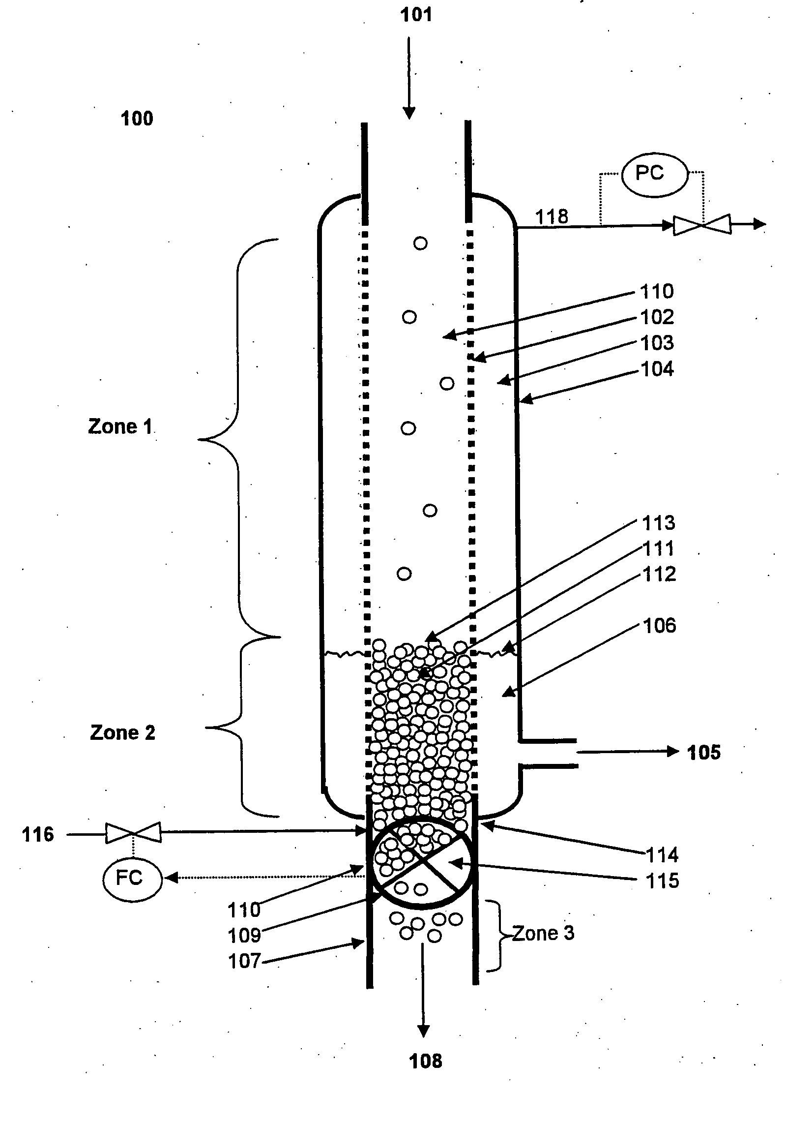
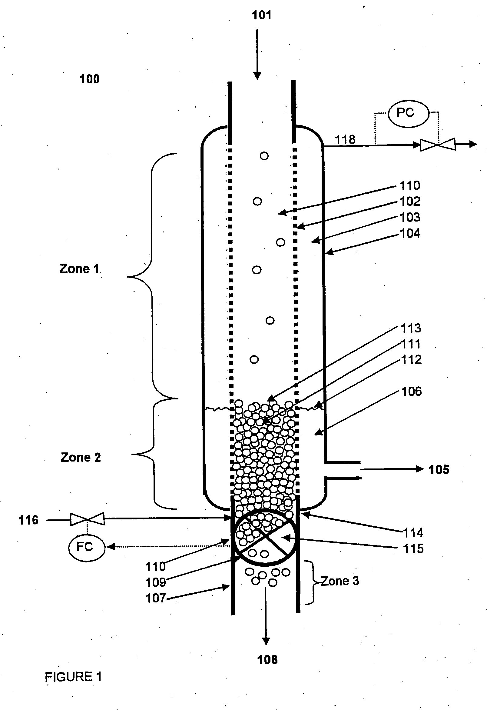
[0066] In a third embodiment, the separation device comprises:

[0067] a. an inlet for continuously receiving a feed of slurry comprising solid particles and a liquid;

[0068] b. a porous filter disposed within the separation device to form an outer annulus receiving the liquid, the outer annulus defined as a space between the wall of the separation device and the filter, said porous filter terminating at a terminal point;

[0069] c. a liquid outlet located on the separation device for discharging at least a portion of said liquid from the outer annulus, wherein the terminal point is located above or in front of the liquid outlet;

[0070] d. a solids outlet for discharging the solid particles in direct or indirect contact with the filter, and

[0071] e. a decoupling device sealed to the solids outlet through which the particles are discharged and under which a pressurized environment within the separation device is maintained at or above the vapor pressure of the liquid.

fourth embodiment

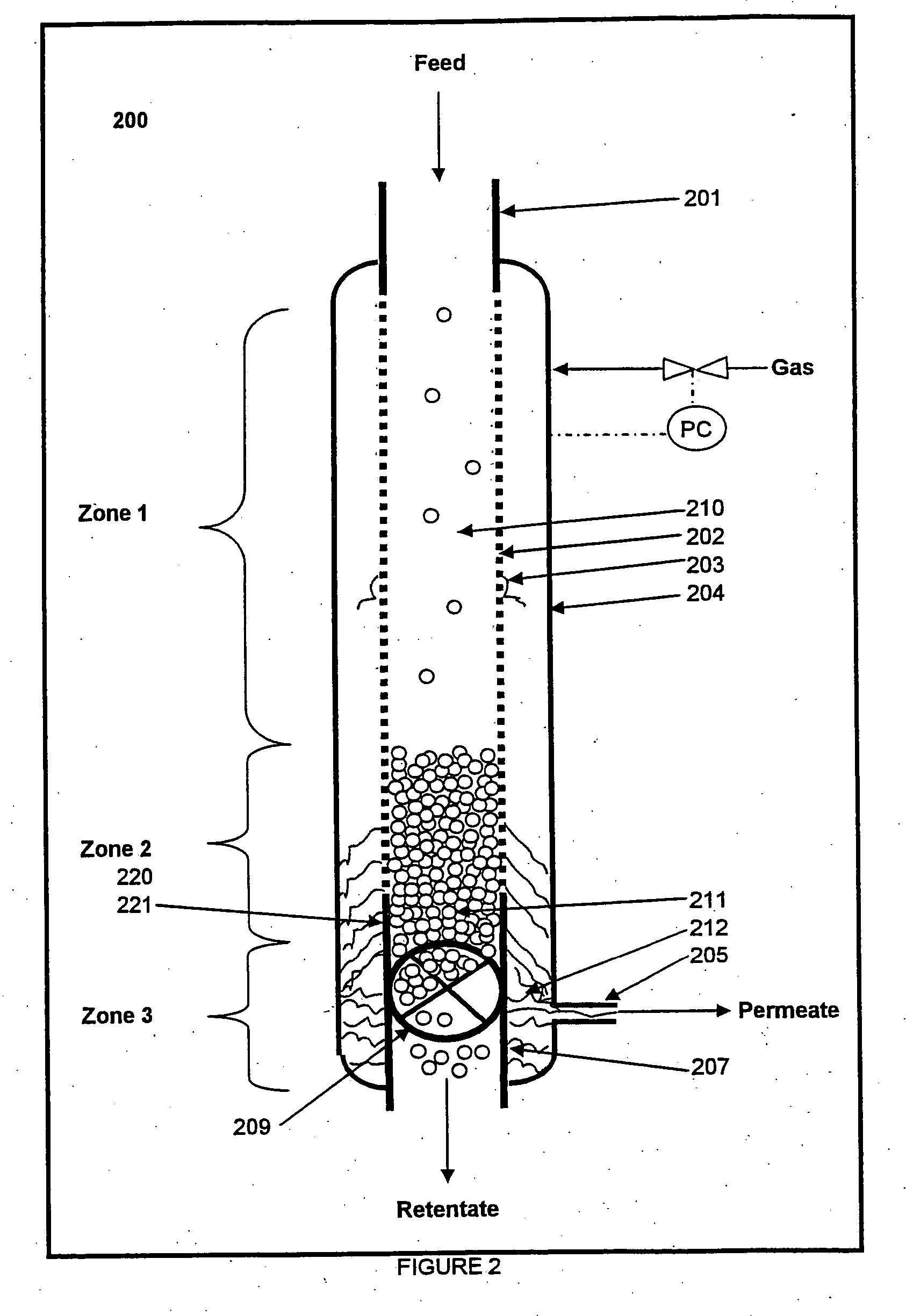
[0072] In a fourth embodiment, there is provided a process for separating particles from a liquid in a slurry comprising:

[0073] a. feeding a slurry comprising solid particles and a liquid into a within a separation zone maintained at a pressure equal to or greater than the vapor pressure of the liquid;

[0074] b. contacting the slurry in the separation zone with a porous filter and separating liquid from the particles, wherein the liquid flows through the filter into an outer annulus defined as a space between the wall of the separation device and the filter, and said porous filter having a terminal point beyond which the separated liquid does not pass from the outer annulus back through the filter;

[0075] c. accumulating no liquid in the outer annulus or accumulating liquid in the outer annulus at a level below or in front of the terminal point, and continuously discharging the separated liquid from the outer annulus through a liquid outlet;

[0076] d. discharging the separated solid...


PUM

PropertyMeasurementUnit
number average particle sizeaaaaaaaaaa
volume percentaaaaaaaaaa
degree of crystallinityaaaaaaaaaa

Abstract

A process and apparatus which reduces the fines in a liquid discharge stream and/or increases the dryness of a solids discharge stream while under a pressure equal to or greater than the vapor pressure of the liquid. There is provided a process for separating particles such as polyethylene terephthalate or polyethylene naphthalate from a liquid in a slurry comprising: a. feeding a slurry comprising solid particles and a liquid into a within a separation zone maintained at a pressure equal to or greater than the vapor pressure of the liquid; b. contacting the slurry in the separation zone with a porous filter, optionally a microfilter, nanofilter, reverse osmosis filter, or ultrafilter, and separating liquid from the particles, wherein the liquid flows through the filter into an outer annulus defined as a space between the wall of the separation device and the filter, and said porous filter optionally having a terminal point beyond which the separated liquid does not pass from the outer annulus back through the filter; c. accumulating no liquid in the outer annulus or accumulating liquid in the outer annulus at a level below or in front of the terminal point, and continuously discharging the separated liquid from the outer annulus through a liquid outlet; d. decoupling the particles from the separation zone through the solids outlet to a low pressure below the vapor pressure of the liquid at the liquid temperature within the separation zone while maintaining a pressure on the particles prior to decoupling at or above the vapor pressure of the liquid within the separation zone.

Description

CROSS REFERENCE TO RELATED APPLICATION [0001] This application claims priority to U.S. Provisional Application Ser. No. 60 / 719,533 filed on Sep. 20, 2005.FIELD OF THE INVENTION [0002] The invention pertains to an apparatus and a process for separating a pressurized slurry of solids and liquid, and more particularly to separating polymeric polymer particles from a hot liquid in a separation device while maintaining the pressure on the solids in the separation device at or above the vapor pressure of the liquid to reduce fines in the liquid or produce a dryer solid or both. BACKGROUND OF THE INVENTION [0003] In previously filed patent applications U.S. Ser. Nos. 10 / 986,129 and 10 / 683,522 and 10 / 665,664, polyester particles are crystallized in a liquid at a temperature above the Tg of the liquid. In many instances, the liquid vapor pressure exceeds atmospheric at such temperature, thereby requiring the application of pressure to retain the fluid in a liquid state. Upon reaching a desir...

Claims


Application Information

Patent Timeline
Patent Type & Authority Applications(United States)
IPC IPC(8): B01D61/00
CPCB01D61/18B01D61/20B01J8/006B01J8/007B01J8/22B01J8/228C08G63/89B01J2208/00672B01J2208/00761B01J2208/00778B01J2219/00162B01J2219/00252B01J2208/00539
Inventor PARKER, KENNY RANDOLPHLIN, ROBERTISAAC, RAYMONDHALL, DUANE ALAN
Owner ALPEK POLYESTER SA DE CV
Why Eureka
Try Eureka