Projection exposure apparatus and stage unit, and exposure method

a technology of projection exposure and stage unit, which is applied in the direction of microlithography exposure apparatus, printers, instruments, etc., can solve the problems of vibration also generated in the substrate table, insufficient margin during the exposure operation, and much shorter wavelength

Inactive Publication Date: 2007-03-22
NIKON CORP
View PDF99 Cites 16 Cited by
  • Summary
  • Abstract
  • Description
  • Claims
  • Application Information

AI Technical Summary

Benefits of technology

[0018] According to this apparatus, the correction unit corrects the positional deviation occurring in at least one of the substrate and the substrate table due to supply of the liquid. Therefore, exposure with high precision in a situation similar to the one under exposure using a dry-type projection exposure apparatus, or more specifically, highly precise exposure that uses the immersion method with respect to the substrate under a situation where positional deviation occurring in at least one of the substrate and the substrate table due to supply of the liquid does not exist, can be achieved.
[0031] In the projection exposure apparatus of the present invention, the substrate table has a fiducial member used for position setting, and the correction unit can correct positional deviation between the fiducial member and the substrate.

Problems solved by technology

And, in order to cope with higher integration of the integrated circuit, it is certain that the exposure wavelength will become much shorter in the future; however, in such a case, the depth of focus may become too narrow so that there may not be enough margin during the exposure operation.
In the conventional art, however, because the liquid is supplied to the space between the front edge section of the optical element on the substrate side of the projection exposure apparatus and the surface of the substrate, that is, the liquid is supplied to a part of the substrate surface, in some cases the substrate or the substrate table on which the substrate is mounted was deformed due to the pressure (the main cause is surface tension and the weight of the water itself) of the liquid, or the distance between the projection optical system and the substrate fluctuated at times. Further, there were times when vibration was also generated in the substrate table, along with the liquid supply.
Such deformation of the substrate or the substrate table described above becomes error factors when measuring the position of the substrate on the substrate table using a laser interferometer.
Especially in the case of a scanning exposure apparatus, unlike a static exposure apparatus (a batch-exposure apparatus) such as the stepper, the change in the distance of the projection optical system and the substrate becomes the cause of positional errors of the substrate in the direction of the optical axis of the projection optical system, which is adjusted based on the output of a focus sensor fixed to the projection optical system.
This was because in the case of a scanning exposure apparatus that performs exposure while moving the substrate stage, when positional errors of the substrate occur in the direction of the optical axis of the projection optical system, the probability was high that a control delay would occur in the focus control of the substrate, even if feedback control was performed on the position of the substrate in the optical axis direction via the substrate stage based on the output of the focus sensor.

Method used


Image

  • Projection exposure apparatus and stage unit, and exposure method
  • Projection exposure apparatus and stage unit, and exposure method
  • Projection exposure apparatus and stage unit, and exposure method

Examples


Embodiment Construction

[0041] An embodiment of the present invention will be described below, referring to FIGS. 1 to 8.

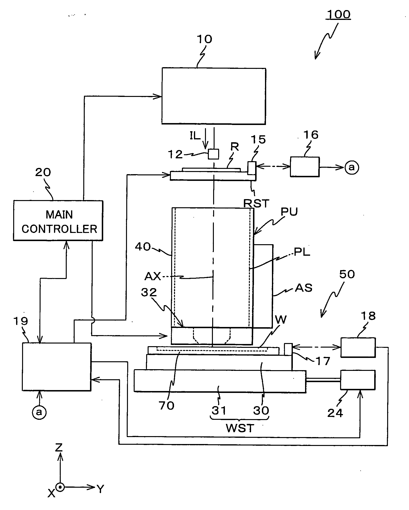
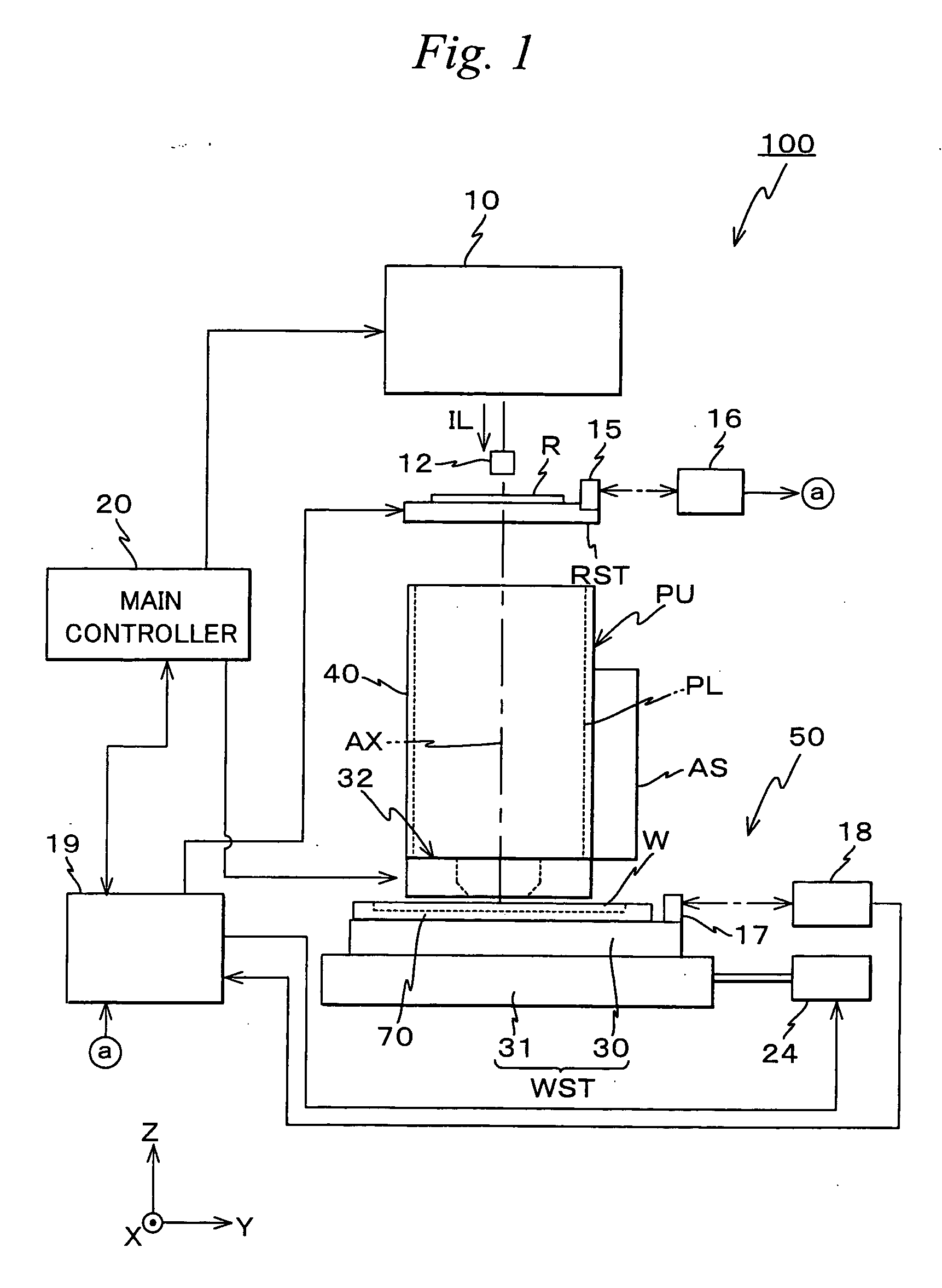
[0042]FIG. 1 shows an entire configuration of a projection exposure apparatus 100 related to the embodiment of the present invention. Projection exposure apparatus 100 is a projection exposure apparatus (the so-called scanning stepper) by the step-and-scan method. Projection exposure apparatus 100 is equipped with an illumination system 10, a reticle stage RST that holds a reticle R serving as a mask, a projection unit PU, a stage unit 50 that has a wafer table 30 serving as a substrate table on which a wafer W serving as a substrate is mounted, a control system for such parts and the like.

[0043] As is disclosed in, for example, Kokai (Japanese Unexamined Patent Application Publication) No. 2001-313250 and its corresponding U.S. Patent Application Publication No. 2003 / 0025890 description or the like, illumination system 10 is configured including a light source, an illuminance uniformi...


PUM

PropertyMeasurementUnit
refractive indexaaaaaaaaaa
wavelengthaaaaaaaaaa

Abstract

A projection exposure apparatus (100) has a substrate table (30) on which a substrate (W) is mounted that can be moved holding the substrate, a position measuring system (18 and others) that measures positional information of the substrate table, and a correction unit (19) that corrects positional deviation occurring in at least either the substrate or the substrate table due to supply of a liquid. In this case, the correction unit corrects the positional deviation occurring in at least either the substrate or the substrate table due to the supply of the liquid. Accordingly, exposure with high precision using a liquid immersion method is performed on the substrate.

Description

[0001] This is a Division of application Ser. No. 10 / 582,488 filed Jun. 12, 2006. The disclosure of the prior application is hereby incorporated by reference herein in its entirety.TECHNICAL FIELD [0002] The present invention relates to projection exposure apparatus and stage units, and exposure methods, and more particularly to a projection exposure apparatus used in a lithography process when manufacturing electronic devices such as a semiconductor device, a liquid display device, or the like and a stage unit suitable for a sample stage of a precision instrument such as the projection exposure apparatus, and an exposure method performed by the exposure apparatus. BACKGROUND ART [0003] In a lithography process for manufacturing electronic devices such as a semiconductor device (such as an integrated circuit), a liquid crystal display device and the like, a projection exposure apparatus is used that transfers an image of a pattern of a mask or a reticle (hereinafter generally referr...

Claims


Application Information

Patent Timeline
Patent Type & Authority Applications(United States)
IPC IPC(8): G03B27/52G03F7/20
CPCG03F7/70716G03F7/70341G03F7/2041
Inventor KAYAMA, YASUNAGAARAI, DAI
Owner NIKON CORP
Why Eureka
Try Eureka