In-vehicle fuel cell system

a fuel cell and vehicle technology, applied in the field of vehicle fuel cell systems, can solve the problems of increasing the large space required for providing such pipes, and the complexity of the piping structure, so as to reduce the length and weight of the pipe, simplify the piping structure, and reduce the effect of pressure loss

Inactive Publication Date: 2007-03-22
HONDA MOTOR CO LTD
View PDF8 Cites 22 Cited by
  • Summary
  • Abstract
  • Description
  • Claims
  • Application Information

AI Technical Summary

Benefits of technology

[0020] A main object of the present invention is to provide an in-vehicle fuel cell system, which makes it possible to simplify the piping structure, reduce the pipe length and weight, and to easily reduce pressure losses.
[0021] Further, another object of the present invention is to provide an in-vehicle fuel cell system, which makes it possible to easily reduce the number of components, by using components having multiple functions, thereby easily reducing the weight of the fuel cell system.
[0022] Further, still another object of the present invention is to provide an in-vehicle fuel cell system, in which the heat of a humidifier can be effectively utilized in order to suitably maintain the temperature of reactant gas auxiliary devices, with a simple and economical structure.

Problems solved by technology

Thus, the piping structure is complicated and the space required for providing such pipes is large.
Thus, the piping structure becomes even more complicated, and the length of the pipes is large.
As a result, pressure losses occur, and further, the weight of the pipes is disadvantageously heavy.
Consequently, in the conventional technique, since dedicated support members are required for respective devices, the number of components is considerably large, the space required for providing such devices is large, and the overall weight of the equipment is heavy.
Thus, uneconomically, excessive electricity is consumed.
Further, the number of components is large, the structure is complicated, and the cost for such equipment is large.

Method used


Image

  • In-vehicle fuel cell system
  • In-vehicle fuel cell system
  • In-vehicle fuel cell system

Examples


Embodiment Construction

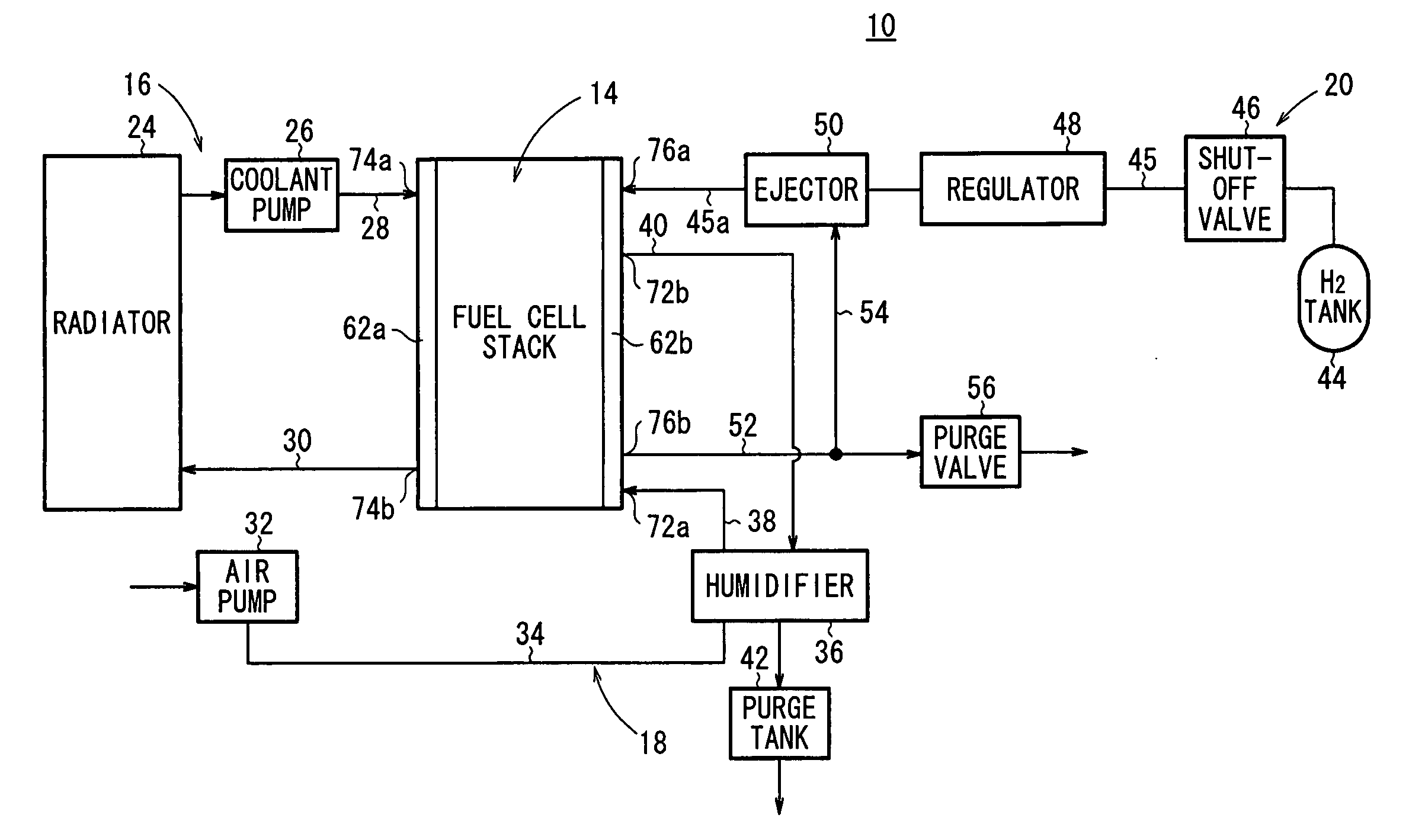
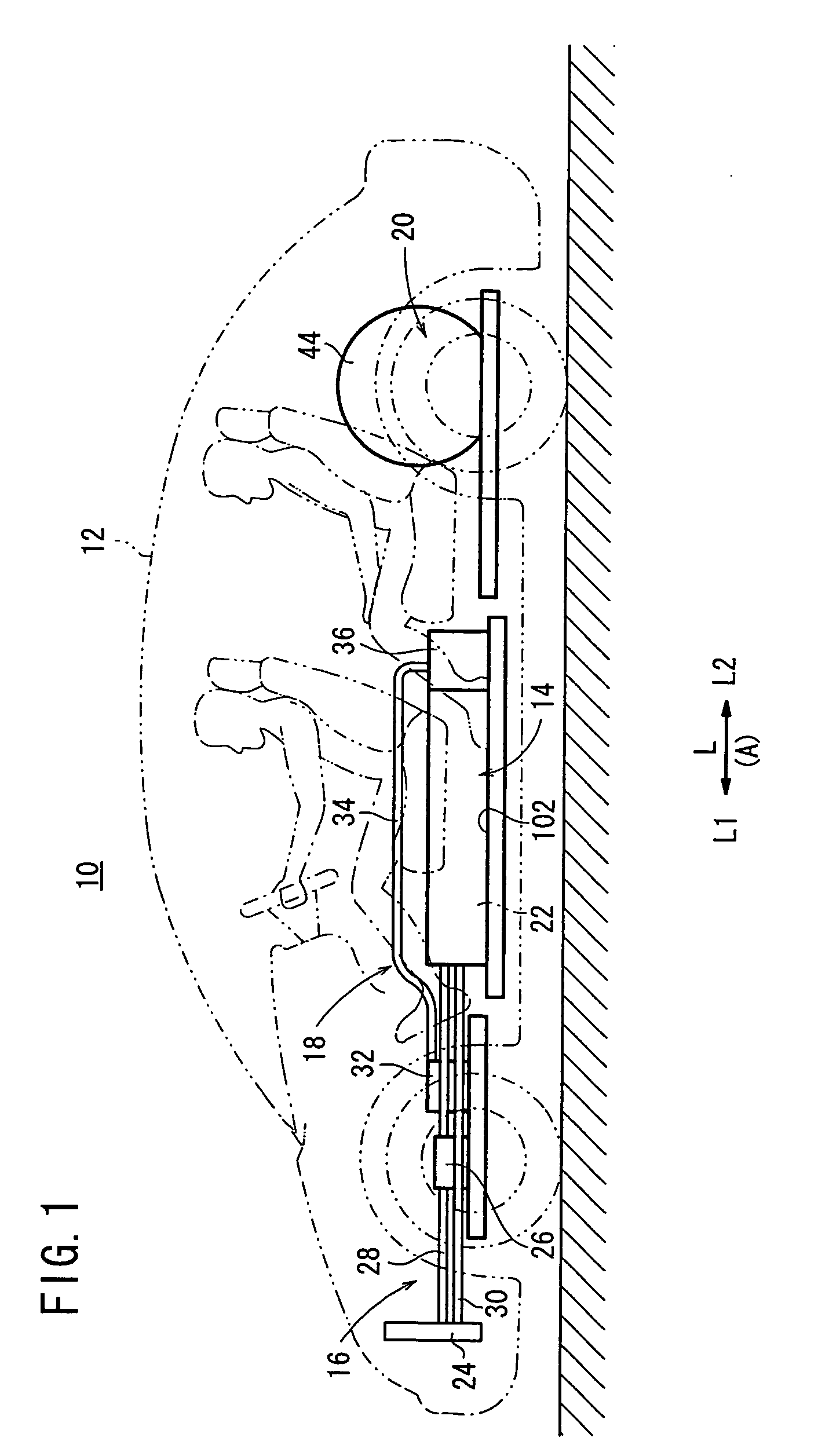
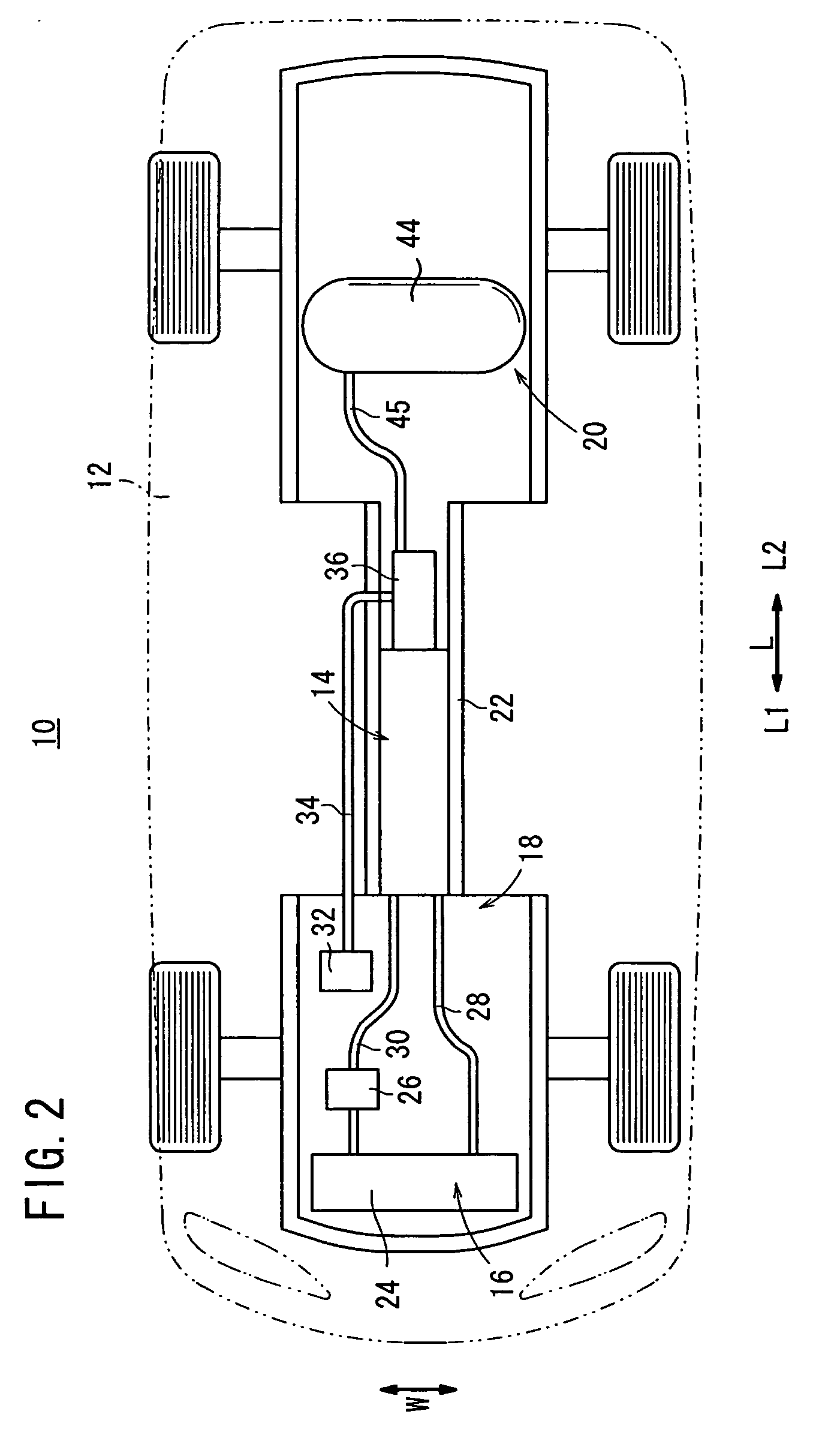
[0050]FIG. 1 is a side view schematically showing a vehicle 12, which is equipped with an in-vehicle fuel cell system 10 according to an embodiment of the present invention. FIG. 2 is a partial plan view of the vehicle 12, principally showing the fuel cell system 10. FIG. 3 is a diagram schematically showing the structure of the fuel cell system 10.

[0051] In FIG. 3, for purposes of illustration, components, to be described in detail later, are shown at positions different from their actual positions. The actual positions of the components are as shown in FIGS. 1 and 2.

[0052] The fuel cell system 10 includes a fuel cell stack 14, a coolant supply mechanism 16 for supplying a coolant to the fuel cell stack 14, an oxygen-containing gas supply mechanism (reactant gas supply mechanism) 18 for supplying an oxygen-containing gas to the fuel cell stack 14, and a fuel gas supply mechanism (reactant gas supply mechanism) 20 for supplying a fuel gas to the fuel cell stack 14.

[0053] The fuel...


PUM

PropertyMeasurementUnit
lengthaaaaaaaaaa
weightaaaaaaaaaa
forceaaaaaaaaaa

Abstract

A fuel cell system mounted in a vehicle includes a fuel cell stack, a coolant supply mechanism, and a fuel gas supply mechanism. The coolant supply mechanism includes a coolant supply pipe and a coolant discharge pipe, provided on a front side in a traveling direction of the vehicle, relative to the fuel cell stack. The fuel gas supply mechanism includes a fuel gas supply pipe, provided on a rear side in the traveling direction, relative to the fuel cell stack.

Description

BACKGROUND OF THE INVENTION [0001] 1. Field of the Invention [0002] The present invention relates to an in-vehicle fuel cell system, including a fuel cell stack formed by stacking a plurality of power generation cells, and which is mounted in a vehicle. [0003] 2. Description of the Related Art [0004] A polymer electrolyte fuel cell employs a membrane electrode assembly (electrolyte electrode assembly), which includes an anode, a cathode, and an electrolyte membrane interposed between the anode and the cathode. The electrolyte membrane forms a polymer ion exchange membrane. The membrane electrode assembly, together with separators sandwiching the membrane electrode assembly, make up a unit of a power generation cell (unit cell) for generating electricity. In use, generally, a predetermined number of unit cells are stacked together to form a fuel cell stack. [0005] In general, a fuel cell stack of this type is mounted in a vehicle such as an automobile to make up a fuel cell vehicle (...

Claims


Application Information

Patent Timeline
Patent Type & Authority Applications(United States)
IPC IPC(8): H01M8/04
CPCH01M8/04089H01M8/04126Y02E60/50Y02T90/32H01M2250/20Y02T90/40
Inventor FUKUMA, KAZUNORINAGUMO, KENJISATO, TAKAHARU
Owner HONDA MOTOR CO LTD
Why Eureka
Try Eureka