Water blocking layer and wicking reservoir for PEMFC

a technology of wicking reservoir and water blocker, which is applied in the field of fuel cells, can solve the problems of reducing affecting the affecting the overall efficiency of the fuel cell,

Inactive Publication Date: 2007-03-22
GM GLOBAL TECH OPERATIONS LLC
View PDF6 Cites 20 Cited by
  • Summary
  • Abstract
  • Description
  • Claims
  • Application Information

AI Technical Summary

Benefits of technology

[0013] In accordance with the teachings of the present invention, a fuel cell that is part of a fuel cell stack in a fuel cell system is disclosed, where the fuel cell includes a water blocking layer positioned between anode gas flow channels and an anode side gas diffusion media layer. The blocking layer prevents liquid water from flowing through the gas diffusion media layer and entering the anode flow channels, while allowing gas from the flow channels to flow through the diffusion media layer to the membrane. A water accumulation channel can be provided around the perimeter of the gas diffusion media layer where blocked water is accumulated, and allowed to expand during cell freezing.

Problems solved by technology

MEAs are relatively expensive to manufacture and require certain conditions for effective operation.
Those areas of the membrane that do not receive input gas as a result of the channel being blocked will not generate electricity, thus resulting in a non-homogenous current distribution and reducing the overall efficiency of the fuel cell.
Significant water accumulation in a single cell could result in severe reactant blockage to that cell and cause the cell to fail.
However, there are many reasons not to use the hydrogen fuel as a purge gas, including reduced economy, reduced system efficiency and increased system complexity for treating elevated concentrations of hydrogen in the exhaust gas stream.
A dry inlet gas has a drying effect on the membrane that could increase the ionic resistance, and limit the membrane's long-term durability.
Accumulated water in the cells can also reduce performance of the fuel cell when operated in an environment where the temperature goes below 0° C. The accumulated water could also lead to mechanical damage in these environments.

Method used


Image

  • Water blocking layer and wicking reservoir for PEMFC
  • Water blocking layer and wicking reservoir for PEMFC
  • Water blocking layer and wicking reservoir for PEMFC

Examples


Embodiment Construction

[0021] The following discussion of the embodiments of the invention directed to a fuel cell including a water blocking layer and a capillary wick is merely exemplary in nature, and is in no way intended to limit the invention or its applications or uses.

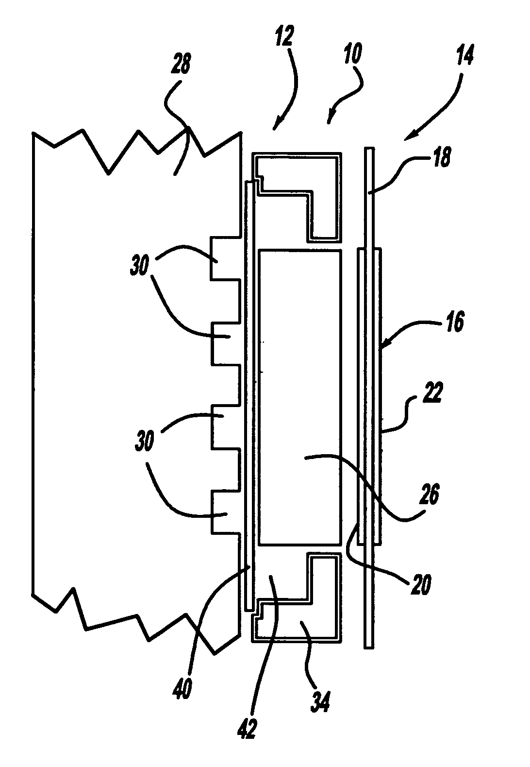
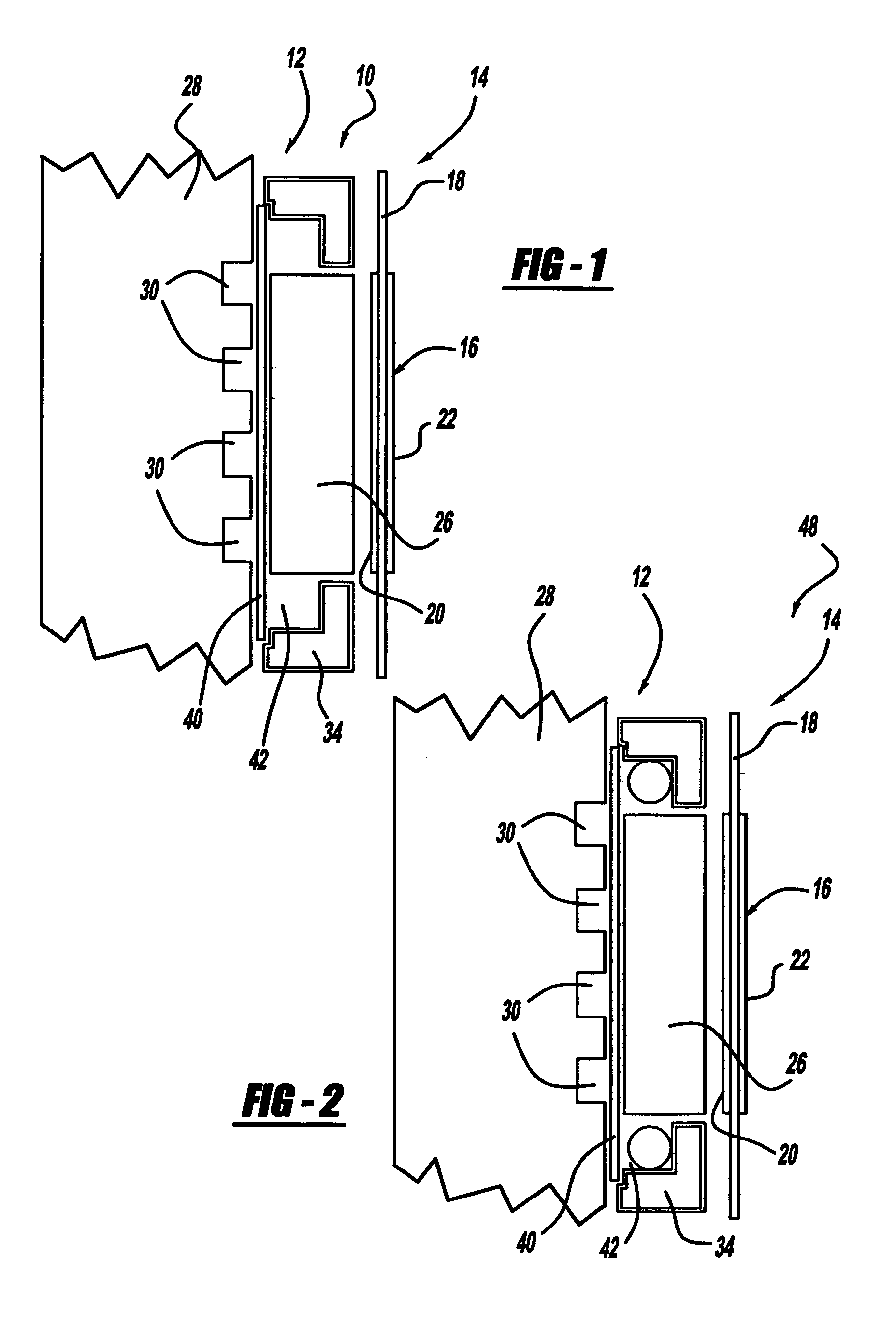
[0022]FIG. 1 is a cross-sectional plan view of a fuel cell 10 that would be one fuel cell in a fuel cell stack, for example, a fuel cell stack in a vehicle. The fuel cell 10 includes an anode side 12 and a cathode side 14. An MEA 16 is positioned between the anode side 12 and the cathode side 14, and includes an electrolyte membrane 18 having a catalyst layer 20 on the anode side 12 of the membrane 18 and a catalyst layer 22 on the cathode side 14 of the membrane 18. An anode side gas diffusion media layer 26 is positioned adjacent to the MEA 16 on the anode side 12 and an anode side bipolar plate 28 is positioned on an opposite side of the gas diffusion media layer 26 from the MEA 16. The anode side bipolar plate 28 includes a seri...


PUM

PropertyMeasurementUnit
thicknessaaaaaaaaaa
temperatureaaaaaaaaaa
diameteraaaaaaaaaa

Abstract

A fuel cell including a water blocking layer positioned between anode gas flow channels and a gas diffusion media. The blocking layer prevents water from propagating through the gas diffusion media layer and entering the anode flow channels, while allowing gas from the flow channels to flow through the diffusion media layer to the membrane. A water accumulation channel can be provided around the perimeter of the gas diffusion media layer where blocked water is accumulated, and allowed to expand during cell freezing. A porous capillary wick can be provided in the accumulation channel for wicking water to the inlet end of the flow channels where it is used to humidify the anode gas coming into the fuel cell. The wick can have a tapered configuration so that it has a larger diameter at the gas input end of the flow channels.

Description

BACKGROUND OF THE INVENTION [0001] 1. Field of the Invention [0002] This invention relates generally to a fuel cell and, more particularly, to a fuel cell employing a water blocking layer for preventing water from entering anode gas delivery channels and a wick positioned within a water accumulation channel for directing water to an inlet end of the anode gas delivery channels. [0003] 2. Discussion of the Related Art [0004] Hydrogen is a very attractive fuel because it is clean and can be used to efficiently produce electricity in a fuel cell. The automotive industry expends significant resources in the development of hydrogen fuel cells as a source of power for vehicles. Such vehicles would be more efficient and generate fewer emissions than today's vehicles employing internal combustion engines. [0005] A hydrogen fuel cell is an electro-chemical device that includes an anode and a cathode with an electrolyte therebetween. The anode receives hydrogen gas and the cathode receives ox...

Claims


Application Information

Patent Timeline
Patent Type & Authority Applications(United States)
IPC IPC(8): H01M8/02H01M8/10H01M4/94
CPCH01M8/0234H01M8/0245H01M8/0247H01M8/04141Y02E60/50H01M8/04171H01M8/04253H01M2008/1095H01M8/04156
Inventor OWEJAN, JON P.JI, CHUNXINTRABOLD, THOMAS A.CARTWRIGHT, MICHAELGOEBEL, STEVEN G.
Owner GM GLOBAL TECH OPERATIONS LLC
Why Eureka
Try Eureka