Multilayer imageable elements having good solvent resistance

a multi-layer imageable element and solvent resistance technology, applied in the field of lithographic printing, can solve the problems of limited resistance of printing plates large residues can accumulate in developers, and many of these systems have limited resistance to fountain solutions and/or aggressive blanket washes, etc., to achieve excellent solvent solubility, excellent chemical resistance, and good solvent resistance

Inactive Publication Date: 2007-03-22
EASTMAN KODAK CO
View PDF27 Cites 15 Cited by
  • Summary
  • Abstract
  • Description
  • Claims
  • Application Information

AI Technical Summary

Benefits of technology

[0016] The imageable elements and the imaged elements prepared therefrom exhibit excellent resistance to the chemicals and solvents used in the preparation and use of lithographic printing plates. In addition, the imageable elements of this invention contain polymeric binders in the outer layer that are very soluble in the developers used for processing. Thus, minimal residue or sludge builds up in the developers. These advantages are achieved by the use of the anhydride-containing polymeric binder in the top layer of the imageable elements. It was surprising that the use of this polymeric binder not only has excellent solubility in the developer but also provides good ink receptivity and developer resistance in the non-exposed regions of the element resulting in good image reproduction.

Problems solved by technology

In addition, the printing plate is often subjected to aggressive blanket washes, such as a “UV wash” to remove ultraviolet curable inks.
However, many of these systems have limited resistance to either fountain solution and / or aggressive blanket washes.
During this step, considerable residue can build up in the developer due to insufficient solubility of removed polymeric binders, particularly polymeric binders from the top layer.
Build up of sludge or residue causes a number of maintenance problems besides lowering the useful life of the developer.

Method used


Image

  • Multilayer imageable elements having good solvent resistance

Examples


example 5

[0186] Imageable elements from Example 2 were placed in a humidity chamber at 40° C. and 80% relative humidity for 1, 3, 7 and 10 days. The aged imageable elements and an imageable element that had not been aged were evaluated as described above, except that imaging energies of 126, 119, 112, 105, 100, 95, 90, 86, 82 and 79 mJ / cm2 were used in the imaging and processing tests. The results are given in Table 4.

TABLE 4Exposure forDeveloperCleanoutbest resolutionDays AgedDrop TestEnergy (mJ / cm2)(mJ / cm2)0210 sec861261240 sec901263210 sec861267240 sec8612610 150 sec86119

examples 6 and 7

[0187] Imageable elements prepared using styrene / maleic anhydride Polymer 2 and Polymer 5 in the top layer were evaluated as described in the General Procedures, except that 956 Developer was used in the developer drop test. The results are given in Table 5. Example 7 required more mechanical agitation in order to completely process the imaged imageable element. This was achieved by increasing the pressure of the plush rollers in the processor.

TABLE 5Exposurefor BestDeveloperCleanoutResolutionExamplePolymerDrop Test(mJ / cm2)(mJ / cm2)Baking test6Polymer 2901007Polymer 5120115   3 min

[0188] The top layer containing Polymer 5 was able to resist deletion up to 3 min. This indicated that some degree of cross-linking had occurred in the coating. Cross-linked coatings provide better run-length on press.

example 8

[0189] An imageable element was prepared by coating two organic layers onto Substrate A. The first coating (basecoat) was applied to Substrate A with a 0.012 inch wire-wound bar. The coating was applied as a 7.0% solution from a mixture of methylethylketone / 1-methoxy-2-propanol / butyrolactone / water (50:30:10:10 by weight) to produce a dry coat weight of 1.5 g / m2. It was dried at a temperature of 125° C. for 35 seconds. The first coating had the following formula:

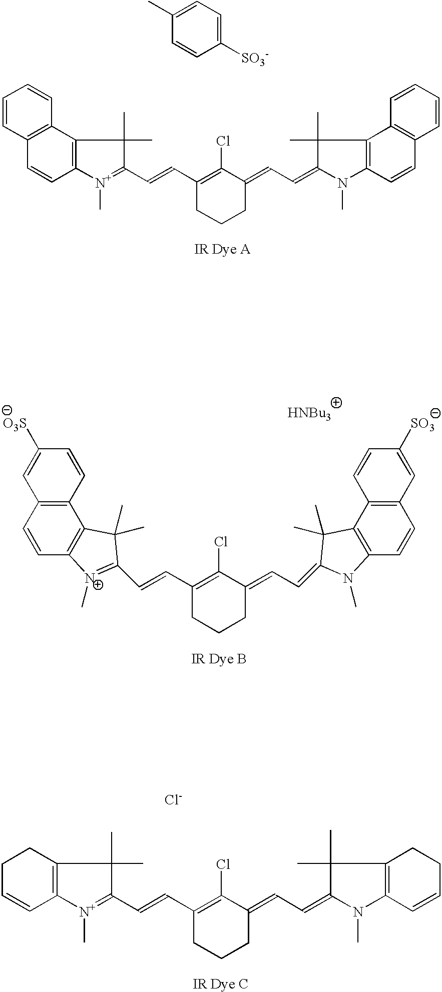
ComponentParts by weightPolymer H84.3IR Dye A15BYK ® 3070.7

[0190] The second organic coating (top layer) was applied on top of the basecoat with a 0.006 inch wire-wound bar. The coating was applied as a 6.0% solution from a mixture of diethylketone / 1-methoxy-2-propanol acetate (92:8 w / w) to produce a dry coat weight of 0.6 g / m2. It was dried at a temperature of 125° C. for 35 seconds. The second coating contained 100 parts by weight of RX-04.

Tests:

[0191] The imageable element was subject to the following tests.

[0192] i)...


PUM

PropertyMeasurementUnit
mol %aaaaaaaaaa
mol %aaaaaaaaaa
mol %aaaaaaaaaa

Abstract

Multilayer thermally imageable elements useful as lithographic printing plate precursors are disclosed. The imageable elements comprise a substrate, an underlayer over the substrate, and a top layer over the underlayer. The top layer contains a polymer containing anhydride groups. This polymer is present in the top layer in an amount of at least 60% based on the dry weight of the layer. The imageable elements have excellent resistance to press room chemicals.

Description

RELATED APPLICATION [0001] This application is a Continuation-in-part of U.S. Ser. No. 11 / 005,548 filed Dec. 6, 2004 by Kitson et al.FIELD OF THE INVENTION [0002] The invention relates to lithographic printing. In particular, this invention relates to multilayer imageable elements useful as lithographic printing plate precursors that have good solvent resistance, and to methods of providing lithographic printing plates therefrom. BACKGROUND OF THE INVENTION [0003] In conventional or “wet” lithographic printing, ink receptive regions, known as image areas, are generated on a hydrophilic surface. When the surface is moistened with water and ink is applied, the hydrophilic regions retain the water and repel the ink, and the ink receptive regions accept the ink and repel the water. The ink is transferred to the surface of a material upon which the image is to be reproduced. Typically, the ink is first transferred to an intermediate blanket, which in turn transfers the ink to the surface...

Claims


Application Information

Patent Timeline
Patent Type & Authority Applications(United States)
IPC IPC(8): G03C3/00
CPCB41C1/1016B41C2210/02B41C2210/06B41C2210/262B41C2210/22B41C2210/24B41C2210/14
Inventor KITSON, ANTHONY P.HUANG, JIANBINGRAY, KEVIN B.
Owner EASTMAN KODAK CO
Why Eureka
Try Eureka