Paired angled rotation scanning probes and methods of use

Inactive Publication Date: 2007-03-22
CALIFORNIA INST OF TECH
View PDF15 Cites 61 Cited by
  • Summary
  • Abstract
  • Description
  • Claims
  • Application Information

AI Technical Summary

Benefits of technology

[0007] The present invention provides forward imaging optical endoscope probes useful in imaging applications, and particularly in imaging applications using OCT as the imaging modality.

Problems solved by technology

The construction of a needle endoscope that is capable of performing forward OCT imaging presents very significant design challenges.
The thickness of such probes, especially when compared with their en face imaging area, e.g., about 2 mm wide, makes them undesirable as a needle endoscope for image-gu

Method used


Image

  • Paired angled rotation scanning probes and methods of use
  • Paired angled rotation scanning probes and methods of use
  • Paired angled rotation scanning probes and methods of use

Examples


Embodiment Construction

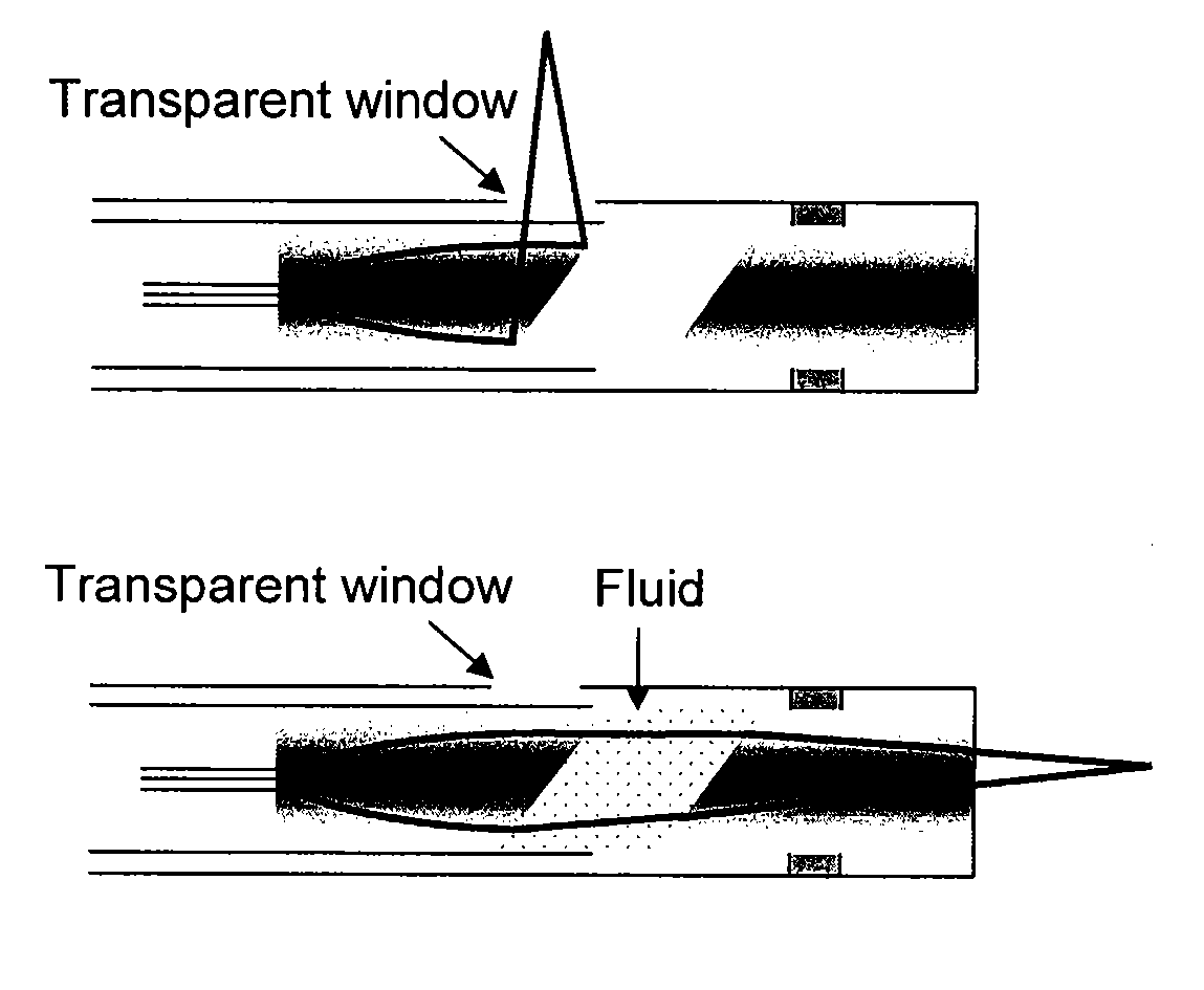
[0024] The present invention provides novel probes, and systems and methods for optically scanning a conical volume in front of a probe, for use with an imaging modality, such as Optical Coherence Tomography (OCT). Other useful imaging modalities for which probes of the present invention are useful include Optical Doppler Tomography (ODT), and Speckle Decorrelation Tomography (SDT).

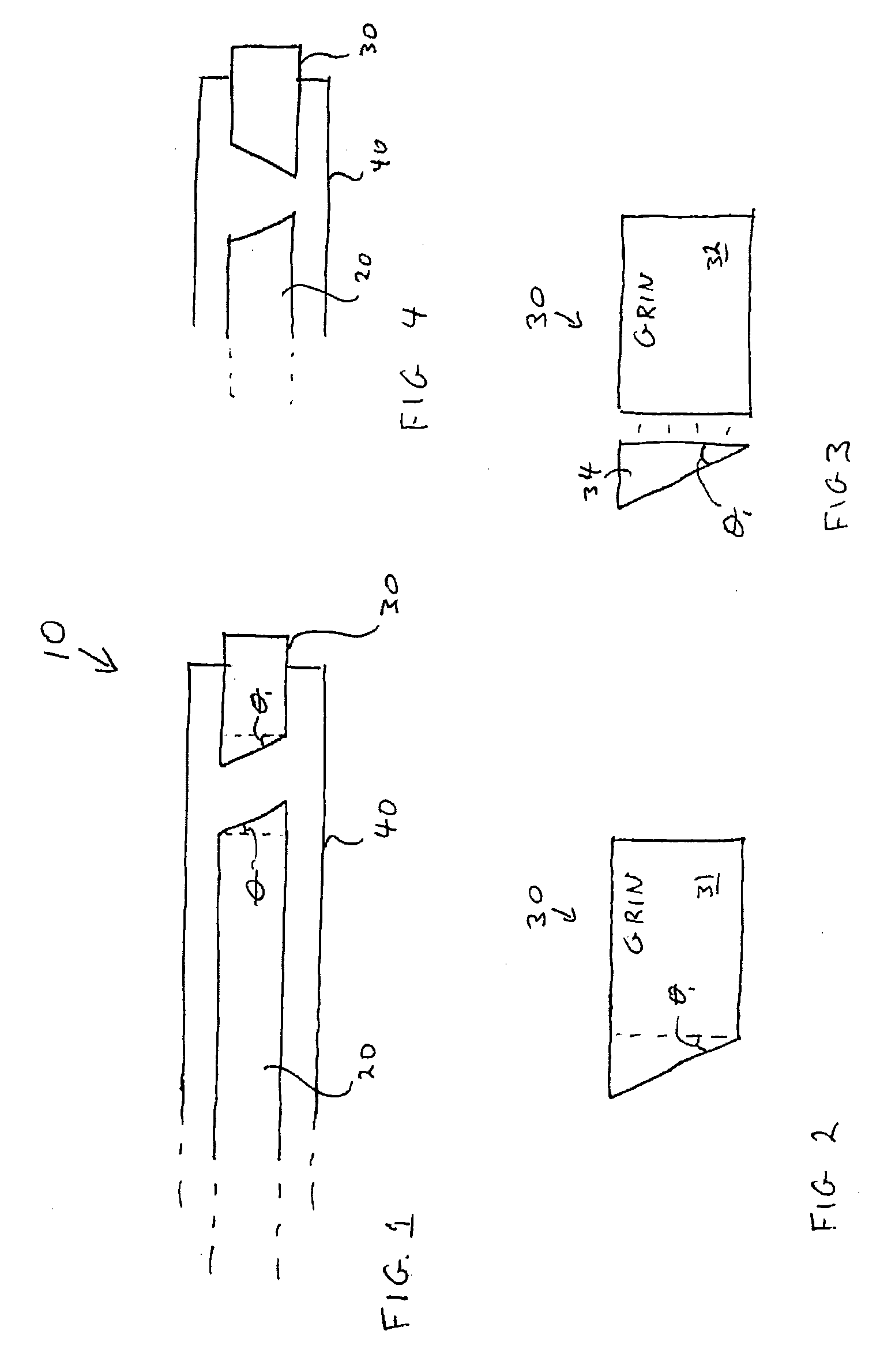
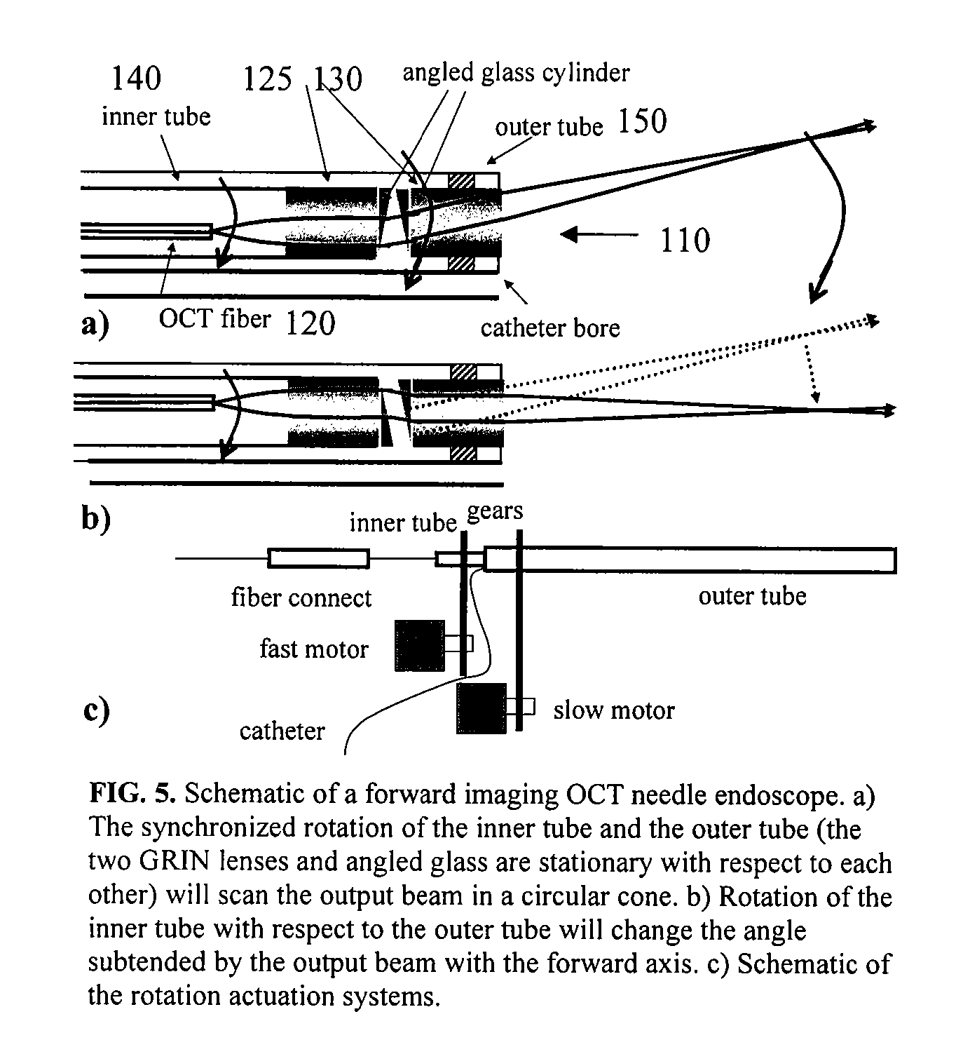
[0025] A probe 10 according to one embodiment is shown in FIG. 1. As shown, probe 10 includes an optical fiber 20 and a lens element 30 proximal the end of fiber 20. A tube 40 encloses fiber 20. Tube 40 is also coupled to lens element 30 to facilitate rotation of lens element 30 relative to fiber 20. Fiber 20 may itself be rotated separately from tube 40, in one aspect, as will be described in more detail below with reference to FIG. 5.

[0026] In one aspect, fiber 20 includes a single mode fiber (SMF; although multimode fibers can be used if desired) having an end that is angled cut at an angle of θ as s...


PUM


Abstract

Probes, and systems and methods for optically scanning a conical volume in front of a probe, for use with an imaging modality, such as Optical Coherence Tomography (OCT). A probe includes an optical fiber having a proximal end and a distal end and defining an axis, with the proximal end of the optical fiber being proximate a light source, and the distal end having a first angled surface. A refractive lens element is positioned proximate the distal end of the optical fiber. The lens element and the fiber end are both configured to separately rotate about the axis so as to image a conical scan volume when light is provided by the source. Reflected light from a sample under investigation is collected by the fiber and analyzed by an imaging system. Such probes may be very compact, e.g., having a diameter 1 mm or less, and are advantageous for use in minimally invasive surgical procedures.

Description

CROSS-REFERENCES TO RELATED APPLICATIONS [0001] This application is a continuation-in-part of U.S. patent application Ser. No. 11 / 087,396, filed Mar. 22, 2005 (Attorney docket No. 020859-005510US), which claims the benefit of U.S. Patent Application No. 60 / 555,628 (Attorney docket No. 020859-005500US; Client Ref. CIT-4060-P), filed Mar. 23, 2004, the disclosures of which are incorporated herein by reference in its entirety. This application also claims the benefit of U.S. Provisional Patent Application Nos. 60 / 770,936, filed Sep. 27, 2005, 60 / 720,934, filed Sep. 27, 2005, and 60 / 737,603, filed Nov. 17, 2005, the disclosures of which are hereby incorporated by reference.STATEMENT AS TO RIGHTS TO INVENTIONS MADE UNDER FEDERALLY SPONSORED RESEARCH OR DEVELOPMENT [0002] The government may have certain rights to the invention based on National Institutes of Health Grant No. 5R21EB004602-02.BACKGROUND OF THE INVENTION [0003] The present invention relates generally to optical probes and mo...

Claims


Application Information

Patent Timeline
IPC IPC(8): A61B1/06
CPCA61B1/00096A61B1/00172A61B5/6852A61B5/0066A61B5/0062
Inventor YANG, CHANGHUEIWU, JIGANG
Owner CALIFORNIA INST OF TECH
Why Eureka
Try Eureka