Pressure measuring system for vacuum chamber using ultrasonic wave

a pressure measurement and vacuum chamber technology, applied in the direction of fluid pressure measurement, pressure difference measurement between multiple valves, instruments, etc., can solve the problems of inability to measure the vacuum pressure, the vacuum leakage at the connection portion, and the like, so as to achieve low vacuum, avoid damage to the device to be measured, and easy to manage and transport

Inactive Publication Date: 2007-03-29
KOREA RES INST OF STANDARDS & SCI
View PDF6 Cites 48 Cited by
  • Summary
  • Abstract
  • Description
  • Claims
  • Application Information

AI Technical Summary

Benefits of technology

[0007] Therefore, the present invention has been made in view of the above problems occurring in the prior art, and a primary object of the present invention to provide a pressure measuring system for a vacuum chamber using the ultrasonic wave, which can minimize the attachment of several sensors mounted through the vacuum chamber to thereby shield the leakage of the vacuum and measure the low vacuum.
[0008] The second object of the present invention is to provide a pressure measuring system for a vacuum chamber using the ultrasonic wave, which can easily measure the inside pressure of a place where it is impossible to mount several sensors or the measuring device for measuring the vacuum.
[0009] The third object of the present invention is to provide a pressure measuring system for a vacuum chamber using the ultrasonic wave, which is simple to manage and transport, and do not give damage to the device to be measured.

Problems solved by technology

However, when several sensors are to be mounted in such chamber, possibility of the leakage of the vacuum at a connection portion, and the like becomes very high.
In addition, it was impossible to measure the vacuum pressure, if it was impossible to mount such sensor or measuring device, or it was impossible to perform the separate mounting work of it.

Method used


Image

  • Pressure measuring system for vacuum chamber using ultrasonic wave
  • Pressure measuring system for vacuum chamber using ultrasonic wave

Examples


Embodiment Construction

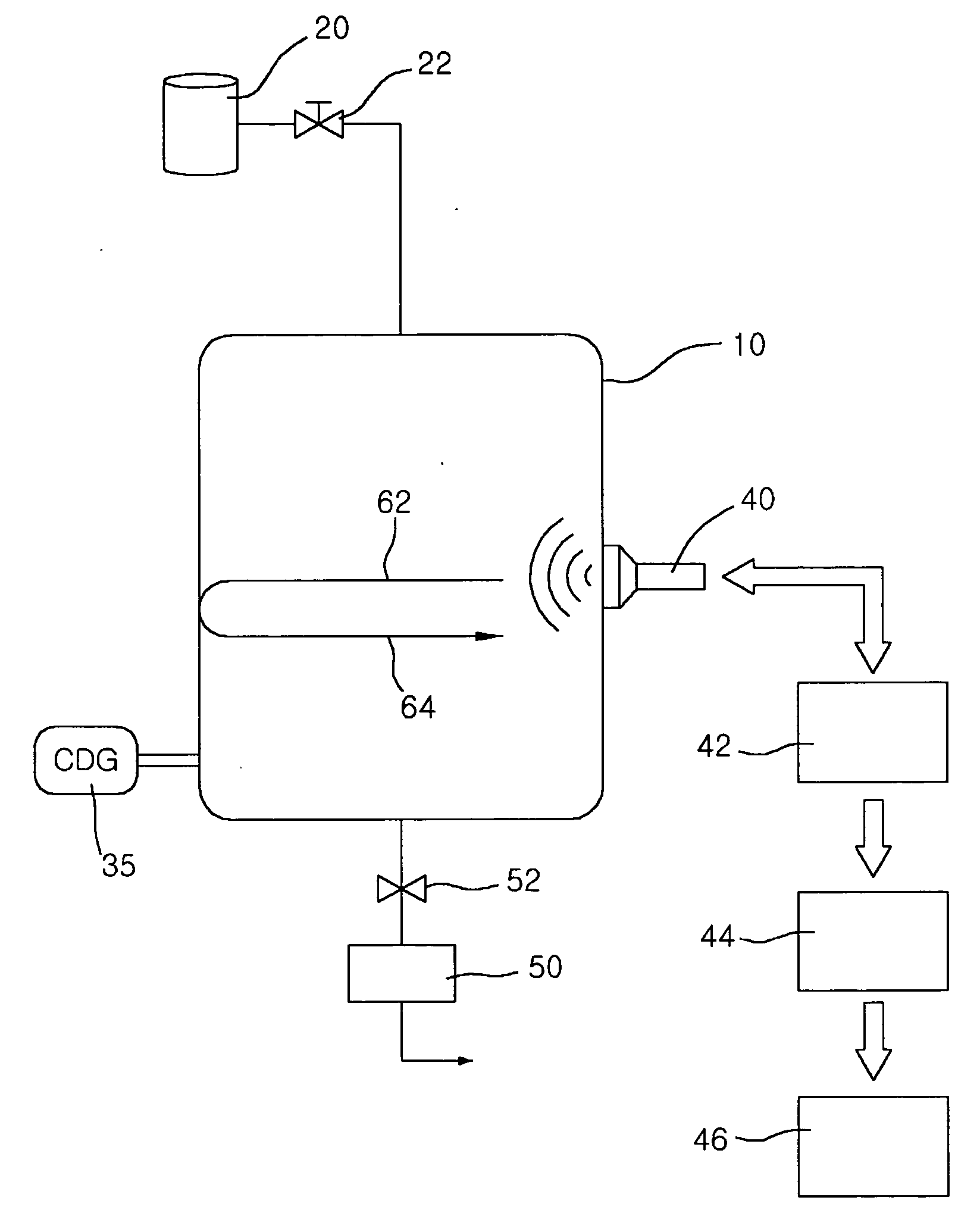
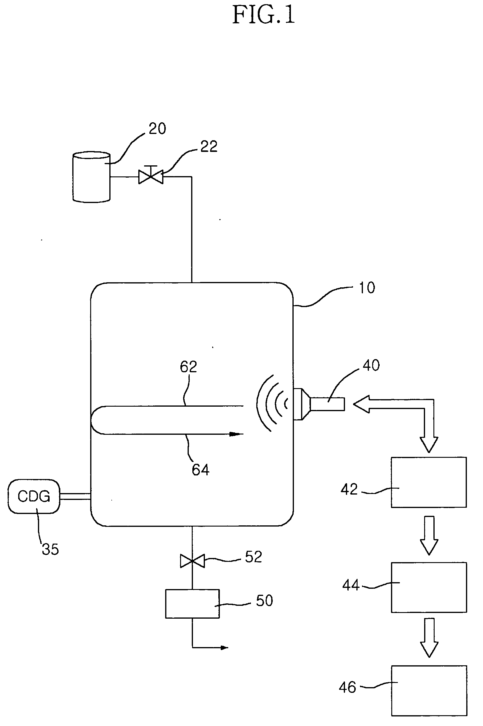
[0012] To accomplish the above objects, according to one aspect of the present invention, there is provided a pressure measuring system for a vacuum chamber using ultrasonic wave, comprising a vacuum chamber formed with desired vacuum at the inside thereof; ultrasonic wave-emitting means mounted close to an outer peripheral surface of the vacuum chamber for emitting an ultrasonic wave to the inside of the vacuum chamber; ultrasonic wave-receiving means for receiving a reflection wave reflected after the striking of the ultrasonic wave emitted from the ultrasonic wave-emitting means to the vacuum chamber; reflection wave-detecting means for detecting the reflection wave from the ultrasonic wave-receiving means; and amplitude-analyzing means for analyzing the amplitude of the reflection wave detected by the reflection wave-detecting means.

[0013] Further, in the present invention, the ultrasonic wave-emitting means and the ultrasonic wave-receiving means may be preferable to be integr...


PUM

PropertyMeasurementUnit
pressureaaaaaaaaaa
vacuum pressureaaaaaaaaaa
pressureaaaaaaaaaa

Abstract

Disclosed is a pressure measuring system for a vacuum chamber, in particular, a pressure measuring system for a vacuum chamber using ultrasonic wave. In this regard, there is provided a pressure measuring system for a vacuum chamber using ultrasonic wave, comprising a vacuum chamber 10 formed with desired vacuum at the inside thereof; ultrasonic wave-emitting means mounted close to an outer peripheral surface of the vacuum chamber 10 for emitting an ultrasonic wave 62 to the inside of the vacuum chamber 10; ultrasonic wave-receiving means for receiving a reflection wave 64 reflected after the striking of the ultrasonic wave 62 emitted from the ultrasonic wave-emitting means to the vacuum chamber; reflection wave-detecting means for detecting the reflection wave 64 from the ultrasonic wave-receiving means; and amplitude-analyzing means for analyzing the amplitude of the reflection wave 64 detected by the reflection wave-detecting means.

Description

BACKGROUND OF THE INVENTION [0001] 1. Field of the Invention [0002] The present invention relates to a pressure measuring system for a vacuum chamber, in particular, to a pressure measuring system for a vacuum chamber using ultrasonic wave. [0003] 2. Background of the Related Art [0004] In general, vacuum chambers used in the fabrication process of the semiconductor and the LCD are at low vacuum state in the range of 1 Pa˜105 Pa, and the pressure measurement of such a low vacuum region is performed by using a CDG (capacitance diaphragm gauge). [0005] Accordingly, the vacuum pressure measurement from now on has been performed by mounting such sensor or measuring device in a vacuum chamber. However, when several sensors are to be mounted in such chamber, possibility of the leakage of the vacuum at a connection portion, and the like becomes very high. As a result, the vacuum leakage should be always checked before the use of the vacuum chamber, or measuring the vacuum pressure. [0006] ...

Claims


Application Information

Patent Timeline
Patent Type & Authority Applications(United States)
IPC IPC(8): G01L11/00
CPCG01L21/08G01L11/06
Inventor HONG, SEUNG SOOSHIN, YONG HYEONCHUNG, KWANG HWA
Owner KOREA RES INST OF STANDARDS & SCI
Why Eureka
Try Eureka