Sensor and sensor module

a sensor module and sensor technology, applied in the field of sensors and sensors, can solve the problems of increasing the power consumption of the sensor which operates with a battery, the inability to equalize the electrostatic force and the pressure, and the imperfect conventional self-diagnosis based on the electrostatic force, etc., and achieves the effect of small power consumption

Inactive Publication Date: 2007-03-29
HITACHI LTD
View PDF3 Cites 62 Cited by
  • Summary
  • Abstract
  • Description
  • Claims
  • Application Information

AI Technical Summary

Benefits of technology

[0008] Therefore, the present invention has been made in view of the above problems, and it is an object of the present invention to provide a sensor and sensor module with small power consumption and high reliability.
[0013] The frequency characteristics (frequency spectrum) of a capacitance between a movable electrode and a fixed electrode can be obtained from measurement of the capacitance under the condition of sweeping the frequency of a control signal (measurement pulse). A resonant frequency can be known on the basis of the fact that the frequency characteristics show a large variation in the vicinity of the resonant frequency. Since the resonant frequency varies with a failure or abnormality occurring in the movable electrode, a self-diagnosis can be performed with respect to whether a sensor is in a normal state or abnormal state, by pre-measuring the resonant frequency, or a frequency at which the movable electrode normally resonates, and determining whether there is a variation in the resonant frequency. By doing this self-diagnosis, it is possible to increase reliability of the sensor.
[0020] According to this invention, it is possible to realize a sensor and sensor module having a self-diagnosis function with small power consumption.

Problems solved by technology

However, conventionally, a high voltage is required for simulation of a physical quantity using an electrostatic force, disadvantageously resulting in an increase in power consumption of a sensor which operates with a battery.
For this failure, it is not possible to equalize the electrostatic force and the pressure, thus making the conventional self-diagnosis based on the electrostatic force imperfect.
In addition, where a part of the movable electrode constituting the sensor fails, a variation in measured value resulting from this failure may be so small that the sensor may output an incorrect pressure using a wrong measurement result.
In this case, it is difficult to perform the conventional self-diagnosis.

Method used


Image

  • Sensor and sensor module
  • Sensor and sensor module
  • Sensor and sensor module

Examples


first embodiment

(First Embodiment)

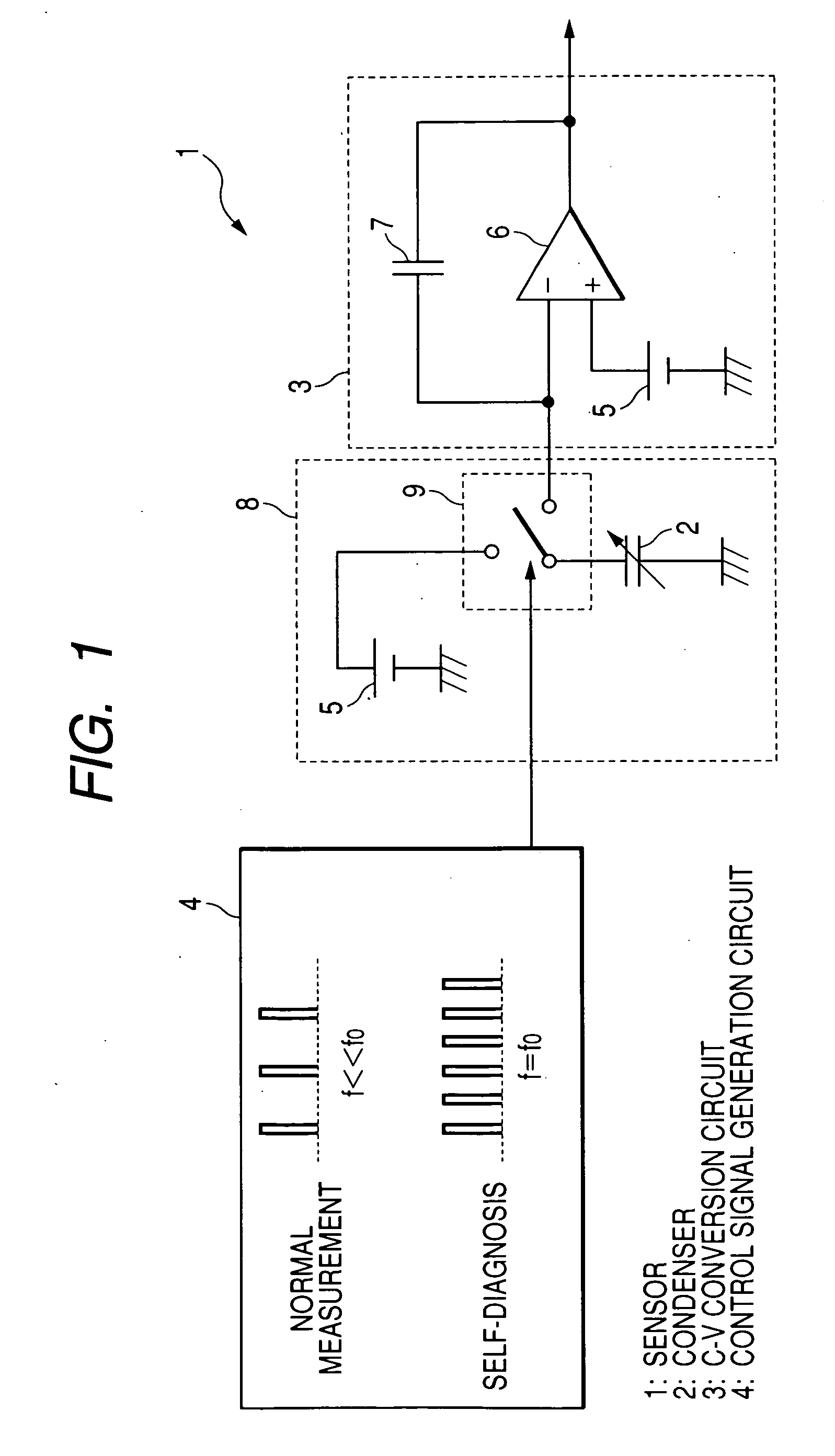
[0034]FIG. 1 is a circuit diagram showing the circuit configuration of a sensor according to a first embodiment of the present invention. As shown in FIG. 1, the sensor according to the first embodiment of the present invention, denoted by reference numeral 1, comprises a switched capacitor circuit 8 including a capacitor 2, a capacitance (C)-voltage (V) conversion circuit 3, and a control signal generation circuit 4. A voltage from a constant voltage source (battery) 5 is supplied to the sensor 1. Although not shown, a signal processing circuit including a low-pass filter (LPF) circuit and an amplifier circuit is disposed at an output side of the C-V conversion circuit 3 (an output terminal side of an operational amplifier 6) to extract and amplify only a signal component of a predetermined frequency band from an output signal from the C-V conversion circuit 3.

[0035] The capacitor 2 is a variable-capacitance capacitor whose capacitance varies with a physical quan...

second embodiment

(Second Embodiment)

[0056] According to a second embodiment of the present invention, a sensor and a sensor module are provided which perform a more reliable self-diagnosis by additionally combining a plurality of methods (self-diagnosis) with the resonant frequency-based method (self-diagnosis) described in the first embodiment. Further, the sensor is included in the sensor module as in the first embodiment. Hereinafter, a description of the second embodiment which duplicates the first embodiment will be omitted.

[0057]FIG. 6 is a circuit diagram showing the circuit configuration of the sensor according to the second embodiment of the present invention, denoted by reference numeral 51. As shown in FIG. 6, the sensor 51 comprises a signal application / switching circuit 52 including the capacitor 2, the C-V conversion circuit 3, and the control signal generation circuit 4. The signal application / switching circuit 52 includes a circuit for applying a constant voltage to the capacitor 2,...


PUM

PropertyMeasurementUnit
voltageaaaaaaaaaa
bias voltageaaaaaaaaaa
capacitanceaaaaaaaaaa

Abstract

A sensor and sensor module with small power consumption and high reliability are disclosed. The sensor includes a capacitor having a capacitance varying with a physical quantity, a capacitance-voltage conversion circuit for converting the capacitance of the capacitor into a voltage, and a control signal generation circuit for generating a plurality of control signals. The capacitor has a frequency-capacitance characteristic with a resonant frequency. In a measurement of the physical quantity, the capacitance of the capacitor is measured with one of the control signals having a first frequency which is much higher or much lower than the resonant frequency. In a self-diagnosis of the sensor, the capacitance of the capacitor is measured with another one of the control signals having a second frequency which is equal or close to the resonant frequency.

Description

CLAIM OF PRIORITY [0001] The present application claims priority from Japanese application JP 2005-277895 filed on Sep. 26, 2005, the content of which is hereby incorporated by reference into this application. FIELD OF THE INVENTION [0002] The present invention relates to a sensor and a sensor module and more particularly to a technique which can be effectively applied to a tire pressure monitoring system (TPMS). BACKGROUND OF THE INVENTION [0003] Disclosed in JP1993-322921A is a technique which performs a self-diagnosis of an electrostatic capacitive sensor having a movable electrode and a fixed electrode arranged to face each other, by applying an electrostatic force to the sensor to simulate deformation and vibration of the structure of the sensor resulting from a certain physical quantity so as to determine whether the sensor normally operates. [0004] Also disclosed in JP2003-121457A is a technique which performs a self-diagnosis of a resonance-based capacitive (electrostatic ca...

Claims


Application Information

Patent Timeline
Patent Type & Authority Applications(United States)
IPC IPC(8): G01L9/12
CPCB60C23/0408G01D5/2417G01L27/007G01L9/12G01L9/0073
Inventor FUJIMORI, TSUKASAYOKOYAMA, NATSUKIFUKUDA, HIROSHIHANAOKA, YUKOAZUMA, TAKASHI
Owner HITACHI LTD
Why Eureka
Try Eureka