
Airborne sampler array

a sampler array and sampler technology, applied in the field of airborne sampler arrays, can solve the problems of not taking unable to take many more than eight samples, and unable to mechanize collection and storage of samples, so as to reduce the potential for sample contamination and sample loss thereby accuracy and sensitivity, and increase the detection limits of some particulates. , the effect of reducing the amount of extraction and the time interval of the sampl

Inactive Publication Date: 2007-03-29
THE UNITED STATES AS REPRESENTED BY THE DEPARTMENT OF ENERGY
View PDF9 Cites 28 Cited by
  • Summary
  • Abstract
  • Description
  • Claims
  • Application Information

AI Technical Summary

Benefits of technology

[0006] A method and device for taking air samples is disclosed. The air sampler of the present invention has relatively few moving parts since it impacts particulates directly into a capture vessel through directional changes of air at a speed established by the sampling method. This sampler device is capable of taking multiple consecutive samples using impaction upon a multi-reservoir capture vessel that is extensively used in laboratory analysis. The method and device described allows limited sample handling thereby reducing the potential for sample contamination and sample loss thereby accuracy and sensitivity. The impaction design optionally removes the need for additional collection media thereby increasing detection limits for some particulates and reducing both the sample time intervals and amount of extraction needed for subsequent analysis.

Problems solved by technology

Very few sampling devices are available that can collect multiple samples.
Those that are available either have problems with use in an indoor public setting (due to air changes / rapid movement, high heat / humidity output, or the large volume of space), do not take many more than eight samples, or are very expensive.
Attempts to mechanize collection and store the samples, such as presented in U.S. Pat. No. 6,138,521, have met with limited success.
Each of these commercially available devices requires extensive sample handling of the media for subsequent analysis—taking time, costing money and involving a high risk of sample cross-contamination.

Method used


Image

  • Airborne sampler array
  • Airborne sampler array
  • Airborne sampler array

Examples


Embodiment Construction

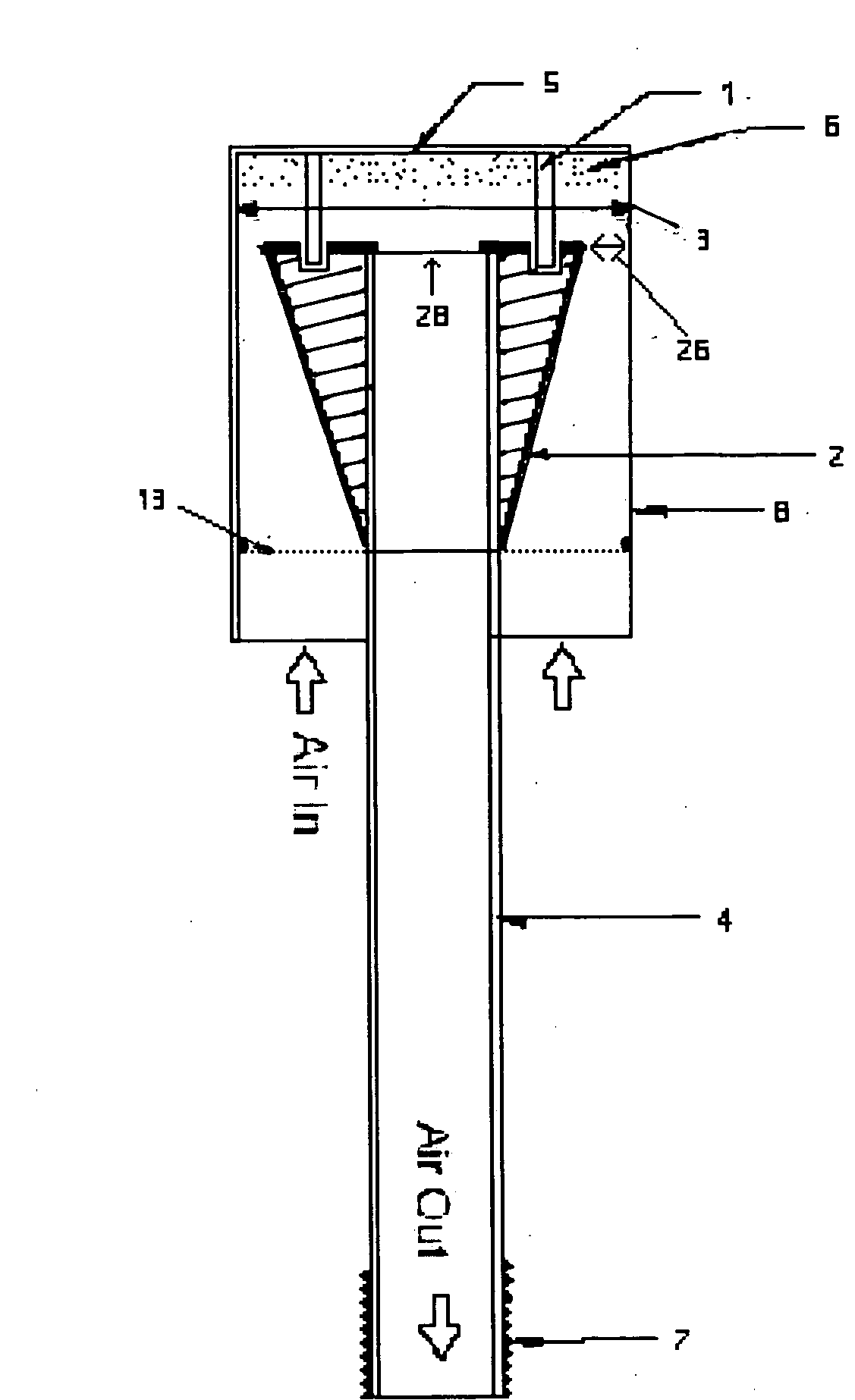
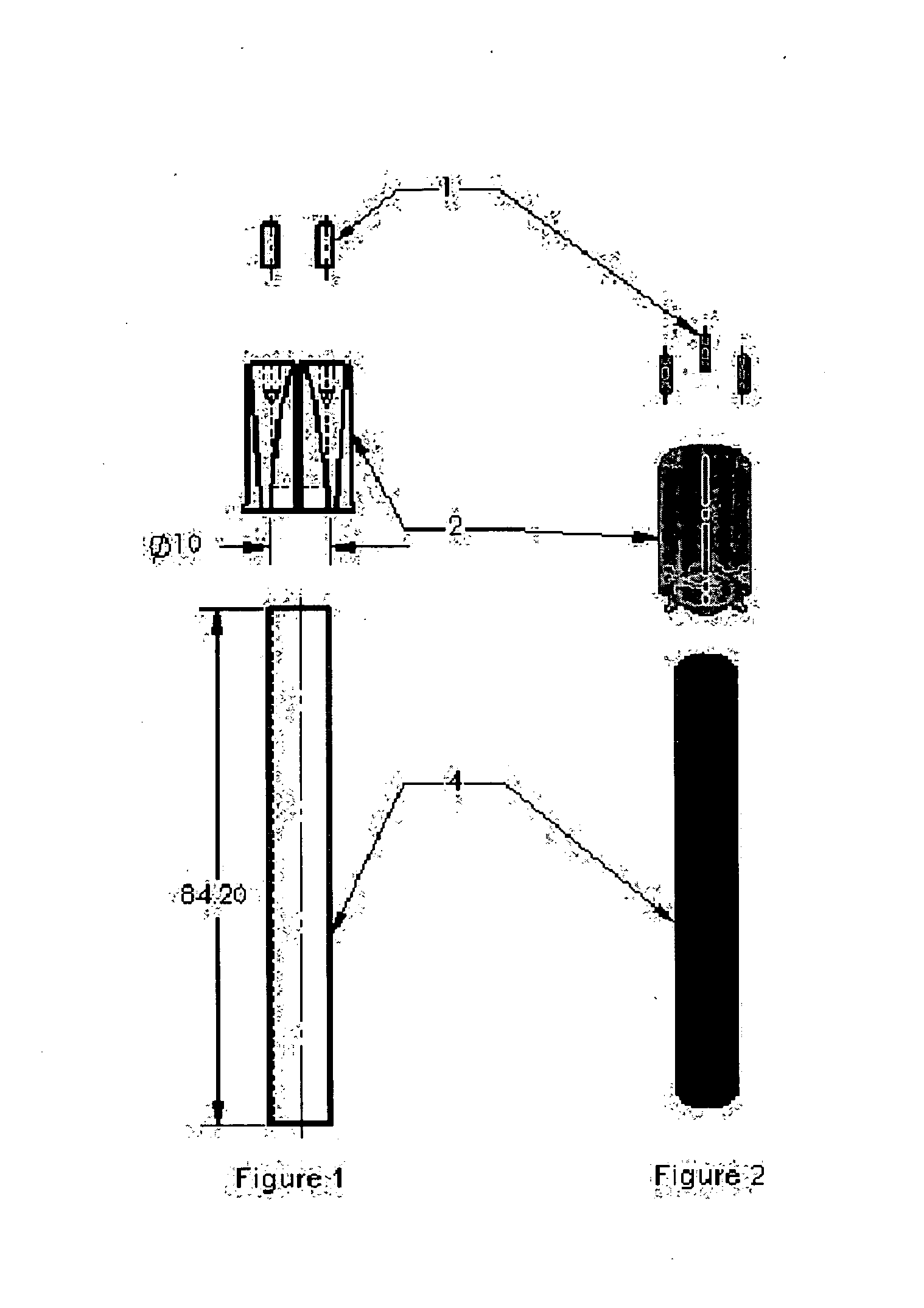
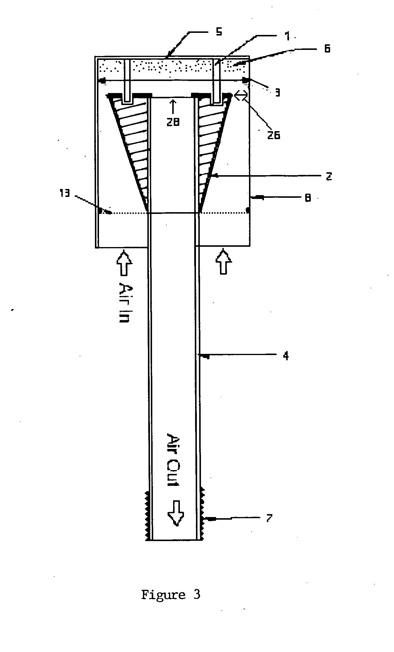
[0013] The airborne sampling device of the present invention employs a nozzle head and impaction format that forces particulate matter onto the internal surfaces a well tray reservoir or other capture vessel for automated analysis. This sampling device shown in it's simplest embodiment in FIGS. 1 and 2, comprises an intake tube 4 onto one end of which is attached a regulating nozzle head 2. The dimensions shown in FIG. 1 are relative and are provided for representation purposes only. Interstitial legs 1 which are inserted into the regulating nozzle 2, as shown in FIG. 3, can be used for mounting the capture vessel 8 spaced above the head as can other means of attachment. The distal end of such air intake tube 4 is fitted with a connection 7 via flexible transfer lines (not shown) to a vacuum pump or other means for the introduction of negative air pressure. The cross sectional view of FIG. 1 indicates recessed indentations in the nozzle head for the acceptance of the interstitial le...


PUM


Abstract

A method and device for collecting airborne particulate samples comprising vacuum air intake tube(s) onto the distal end of each of which is connected a regulating nozzle that is covered by the well reservoir of a capture vessel. Ambient air is directed to impact the interior surfaces of a single or multi-reservoir capture vessel. Each such well reservoir may include additional collector media and can be fitted with a filter screen. A plurality of said intake tubes may also be assembled and automated for programmable sample times and duration through a manifold in order to service a standard well tray which provides for higher collection efficiencies. In situ pathogen detection is possible by inclusion of nucleic acid specific dyes or probes in the media and / or by attachment of an excitation light, radiation detector, or fluorometer device(s) focused on the internal surfaces of a semi-translucent well reservoir.

Description

STATEMENT REGARDING FEDERAL RIGHTS [0001] This invention was made with Government support under Contract No. W-7405-ENG-36 awarded by the U.S. Department of Energy. The Government has certain rights in the invention.FIELD OF THE INVENTION [0002] The present invention relates generally to a device and method used for the collection of airborne particulate samples using impaction and / or filtration in an assembly such that the nozzle heads are configured to coincide with the reservoirs of a capture vessel for programmable interval times / duration and easy transfer of the samples for laboratory analysis. The sampling device can be adapted for use remotely where it is desired to conduct a variety of sample analyses on site or in real time. BACKGROUND OF THE INVENTION [0003] The collection of airborne particulate samples across the country for subsequent laboratory analysis is in need of automation. Very few sampling devices are available that can collect multiple samples. Short duration s...

Claims


Application Information

Patent Timeline
IPC IPC(8): G01N1/22
CPCG01N1/2205
Inventor CASTRO, ALONSOLOPEZ, RICKY C.MOORE, MURRAY E.CREEK, KATHRYN L.GRAY, PERRY C.
Owner THE UNITED STATES AS REPRESENTED BY THE DEPARTMENT OF ENERGY
Learn More