Valve, in particular for a high-pressure pump of a fuel injection system for an internal combustion engine

a technology of high-pressure pump and internal combustion engine, which is applied in the field of valves, can solve the problems of large tooling, large amount of material removal, and complicated machining of the seat fa

Active Publication Date: 2007-03-29
ROBERT BOSCH GMBH
View PDF23 Cites 19 Cited by
  • Summary
  • Abstract
  • Description
  • Claims
  • Application Information

AI Technical Summary

Benefits of technology

[0004] In the dependent claims, advantageous features and refinements of the valve of the invention are disclosed. The embodiments according to claims 2 and 3 make a further reduction in the size of the seat face possible and hence a simplification of its machining and a further reduction in the flow losses. The embodiment according to claim 4 likewise makes a further reduction in flow losses possible. The high-pressure pump of the invention having the characteristics of claim 7 has the advantage that it is simple to manufacture, and a good flow from its inlet valve and / or outlet valve is attained.

Problems solved by technology

This requires complicated machining of the seat face, for instance by means of grinding.
In the known valve, the seat face is large, so that its machining requires a large tool and is time-consuming and under some circumstances leads to the removal of a large amount of material.
If the housing part of the high-pressure pump is hardened, the hardened surface layer of the housing part might be removed under some circumstances, and in that case there is no longer adequate strength of the seat face, which is hence subject to severe wear.
Furthermore, the flow through the known valve is not optimal, because of the major flow deflection and the attendant flow losses of the seat face.

Method used


Image

  • Valve, in particular for a high-pressure pump of a fuel injection system for an internal combustion engine
  • Valve, in particular for a high-pressure pump of a fuel injection system for an internal combustion engine
  • Valve, in particular for a high-pressure pump of a fuel injection system for an internal combustion engine

Examples


Embodiment Construction

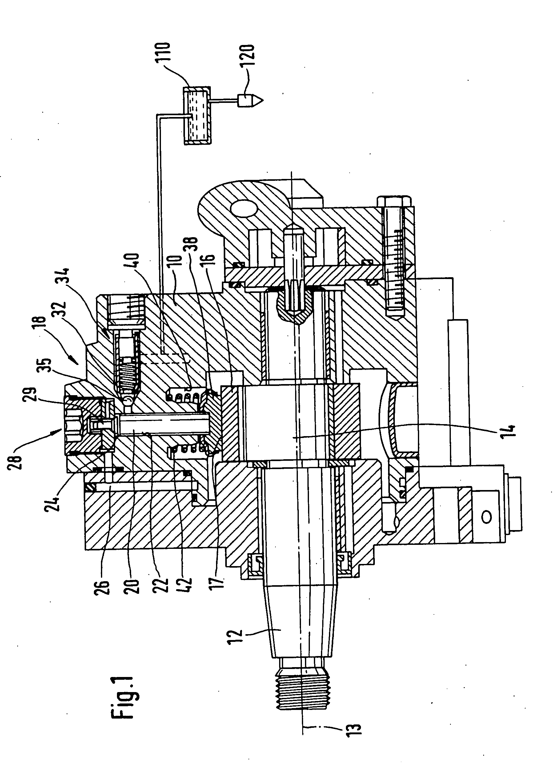
[0012] In FIGS. 1 through 6, a high-pressure pump for a fuel injection system of an internal combustion engine is shown. The high-pressure pump, as shown in FIG. 1, has a housing 10, which is embodied in multiple parts and in which a drive shaft 12 is disposed. The drive shaft 12 is supported rotatably in the housing 10 and is driven to rotate by the engine in a manner not shown in further detail.

[0013] The drive shaft 12 has a shaft portion 14, embodied eccentrically to its axis of rotation 13, on which a transmission element 16 in the form of a polygonal ring is rotatably supported. The high-pressure pump has at least one and preferably a plurality of pump elements 18 disposed in the housing 10, each having a pump piston 20 that is driven by the polygonal ring 16 in a reciprocating motion in an at least approximately radial direction to the axis of rotation 13 of the drive shaft 12. The pump piston 20 is guided tightly displaceably in a cylinder bore 22 in the housing 10, or in a...


PUM


Abstract

A valve having a valve member, which cooperates with a valve seat formed in a housing part in order to control a connection, and the valve seat has an at least approximately conical seat face, which is located at a transition of the connection from a portion of small diameter to a portion of large diameter. The seat face is adjoined, on its side oriented toward the portion of large diameter, by at least one face which is more markedly inclined relative to the longitudinal axis of the connection than the seat face, and on its side oriented toward the portion of small diameter, the seat face is adjoined by at least one face which is less markedly inclined relative to the longitudinal axis of the connection than the seat face.

Description

PRIOR ART [0001] The invention is based on a valve, in particular for a high-pressure pump of a fuel injection system for an internal combustion engine, as generically defined by the preamble to claim 1. [0002] A high-pressure pump with such a valve is known from German Patent Disclosure DE 197 44 577 A1. This high-pressure pump has a housing in which the valve, embodied as a check valve, is disposed. The valve has a valve member in the form of a ball, which cooperates with a valve seat formed in the housing part in order to open and close a communication of a pump work chamber of the high-pressure pump with a fuel outlet. The valve seat has an at least approximately conical seat face. To achieve sure sealing of the valve seat by the valve member, the shape of the seat face in terms of roundness and its surface smoothness must be manufactured very precisely. This requires complicated machining of the seat face, for instance by means of grinding. In the known valve, the seat face is ...

Claims


Application Information

Patent Timeline
Patent Type & Authority Applications(United States)
IPC IPC(8): F16K15/04F02M59/46F02M63/02F04B53/10
CPCF02M59/462F02M63/0225F02M59/464F16K15/044F04B53/1007Y10T137/7927
Inventor VAN DER LINDEN, DIETMARFUCHS, WALTERDUTT, ANDREASTUCHEL, DIETER
Owner ROBERT BOSCH GMBH
Why Eureka
Try Eureka