
Fiber chopper with improved idler roll

a fiber chopper and idler roll technology, applied in glass making apparatus, manufacturing tools, grain treatment, etc., can solve the problems of chopper being the most productivity limiting equipment, difficult to pull all strands and fibers at the same time, and more frequent breakouts and/or additional fiber diameter variations, so as to increase the longevity of rotating idler roll components

Active Publication Date: 2007-03-29
JOHNS MANVILLE CORP
View PDF3 Cites 6 Cited by
  • Summary
  • Abstract
  • Description
  • Claims
  • Application Information

AI Technical Summary

Benefits of technology

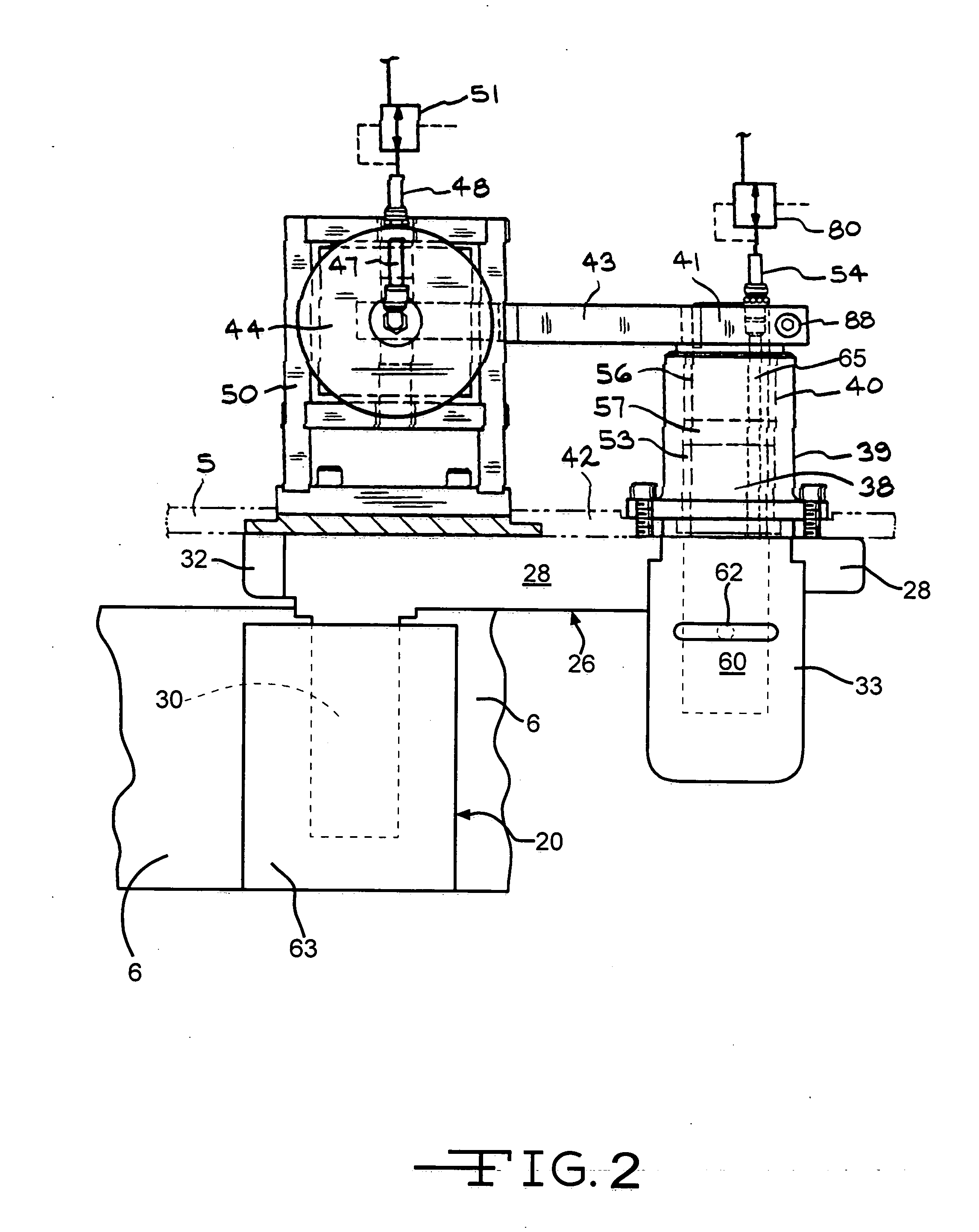
[0008] The chopper for separating long lengths of unwound item(s) selected from the group consisting of fibers, fiber strands, string, yarn, wire, tape and ribbon into short pieces comprising a frame having a front plate on an outboard, operating side of the chopper, a rotatable backup roll outboard of the front plate, the backup roll having an elastomeric peripheral working surface, a rotatable blade or cutter roll outboard of the front plate, a rotatable idler roll mounted outboard of the front plate for pressing the item(s) against said working surface of the backup roll and an idler roll mount for holding the idler roll and applying a force to press the idler roll against the item(s) to be chopped and the working layer on the backup roll as the latter rotates. The improved chopper has an idler roll assembly comprising an idler roll, a hub and pin for pivotally attaching to the axle and at least one bearing between the idler roll and the hub to permit the idler roll to rotate around the hub while the hub is free to pivot to keep the idler roll in contact with the items on the working surface. The improved chopper can also optionally further comprise an idler roll mount assembly comprising a support arm for mounting the idler roll assembly. The idler roll assembly can optionally further comprise a biasing member for impeding the idler roll from pivoting downwardly when the idler roll is raised off of the working surface of the backup roll. The improved chopper can also optionally further comprise a fluid purge system that forces a fluid through the interior of the idler roll assembly to prevent foreign matter from entering the idler roll assembly and impeding pivoting and / or rotation of the idler roll and also optionally through a portion of the idler roll mount assembly to prevent foreign matter from getting into moving parts exposed to the atmosphere outside the chopper. This fluid purge system would also provide some cooling effect to help increase the longevity of rotating idler roll components.

Problems solved by technology

In the chopped fiber processes disclosed in these patents, the chopper is usually the most productivity limiting equipment in the processes that are round the clock, 24 hours per day, type processes.
As more fiber strands and fibers are fed into the chopper it becomes more difficult to pull all of the strands and fibers at the same speed, so more pressure is applied to the cylinder pushing the idler roll against the backup roll with more force.
If all of the strands or fibers are not pulled at the same speed, the slower strands and fibers will have a greater fiber diameter which is unacceptable and the bushings of the slower strands frequently will not operate at the proper temperature causing more frequent breakouts and / or additional fiber diameter variations, both of which are unacceptable.
Also, fiber slippage can cause some of the fibers to be cut to shorter lengths than desired resulting in an unacceptable product.
Also, if all of the strands are not pressed between the idler roll and the elastomer layer of the backup roll, a strand can slip partially out of the nip leaving some of the fibers unchopped, producing double cuts and stringers in the chopped product and causing the product to be scrapped.
This condition worsens as the backup roll and blades become worn with use, typically about 6-24 hours following a chopper rebuild in which the blade roll is replaced with a roll having new blades and the backup roll is replaced with either a refurbished or new backup roll.
An improved idler roll mount is disclosed in U.S. Pat. No. 6,723,670, and this mount works very well but requires the entire yoke to pivot to keep the idler roll in the desired alignment and this added inertia is a disadvantage, especially at high pulling speeds above about 3000 FPM.

Method used


Image

  • Fiber chopper with improved idler roll
  • Fiber chopper with improved idler roll
  • Fiber chopper with improved idler roll

Examples


Embodiment Construction

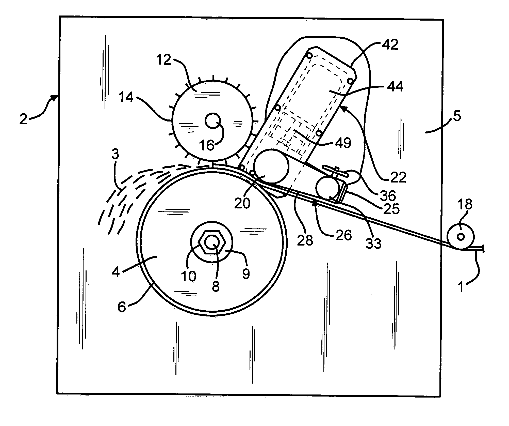
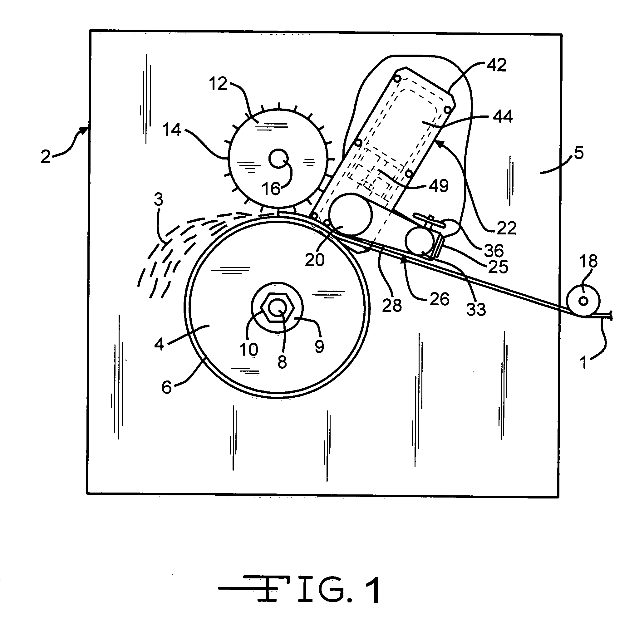
[0020]FIG. 1 shows a chopper 2 for separating long items such as fibers, fiber strands, strings, wires, tape(s) or ribbon(s) 1 into short lengths 3. Typically the short lengths are about 4 or 5 inches or less, but can be longer if the diameter of the blade roll 12 and the backup roll 4 are more than about one meter. For purposes of describing the invention an improved chopper 2 for separating long fiber strands, such as glass fiber strands, is illustrated. Such a chopper typically comprises a backup roll 4 having an elastomer layer 6 on its outer periphery and mounted on a rotating spindle 8 and held on with a large washer 9 and nut 10, a blade roll 12 having blades 14 spaced apart around its outer periphery and mounted on a rotating spindle 16 in a similar manner as the backup roll 4. The typical chopper also comprises a front plate 5, which preferably is an element of a conventional chopper frame (not shown) and a rotating idler roll 20 having a knurled surface that is pressed aga...


PUM

PropertyMeasurementUnit
Forceaaaaaaaaaa
Pressureaaaaaaaaaa

Abstract

A method and apparatus for chopping long unwound items like fiber, fiber strands, yarn, etc. having an idler roll for pressing the item(s) against a backup roll for pulling the item(s) into the chopper, the idler roll being an assembly allowing the idler roll to pivot around a pin inside the idler roll assembly to keep the surface of the idler roll in proper contact with the items being chopped.

Description

BACKGROUND [0001] The present invention involves an improved chopper for chopping continuous or very long loose items such as fiber, fiber strands, yarn, wire, string, ribbon, tape and the like by pulling the item(s) into the chopper while the loose items are held tightly against the surface of a rotating backup roll with a rotating idler roll biased against the backup roll and carrying the item(s) on into a nip between a rotating blade roll and the rotating backup roll where they are separated into short pieces. More specifically the present invention involves a chopper having an improved idler roll which allows the idler roll to reliably self align with the surface of a back up roll to more reliably and more effectively hold down and pull item(s) being pulled and chopped such as loose wet or dry strands of glass fibers with, or without, a chemical sizing thereon. [0002] It has long been known to chop continuous fibers or fiber strands into short lengths of about 3 inches or shorte...

Claims


Application Information

Patent Timeline
IPC IPC(8): B02C18/16
CPCD01G1/04C03B37/16
Inventor BASCOM, RANDALL CLARKTORBETT, GLENN ALLEN
Owner JOHNS MANVILLE CORP
Learn More