Resonant optical scanner using vibrating body with optimized resonant frequency characteristics and image forming apparatus having the same

a vibrating body and optical scanner technology, applied in the field of optical scanning techniques, can solve the problems of disturbing vibration, torsional vibration is likely to occur, disturbing vibration is unwantedly superimposed on the torsional vibration in the vibrating body,

Inactive Publication Date: 2007-03-29
BROTHER KOGYO KK
View PDF5 Cites 22 Cited by
  • Summary
  • Abstract
  • Description
  • Claims
  • Application Information

AI Technical Summary

Benefits of technology

[0016] For a vibrating body that the present inventors have focused on, when the shape of the vibrating body is configured so as to exhibit a higher resonant frequency of a torsional vibration, a resonant frequency of a disturbing vibration strongly greatly tends to be close to a resonant frequency of the torsional vibration, and becomes coincide with the resonant frequency of

Problems solved by technology

In the aforementioned optical scanning apparatuses, in which optical scanning is performed using a torsional vibration of the vibrating body, not only the torsional vibration but also an unwanted disturbing vibration which is other than the torsional vibration is likely to occur.
However, when a resonant frequency of a torsional vibration and a resonant frequency of a disturbing vibration are equal or close to each other, even if the vibrating body is vibrated at the same frequency as the resonant frequency of the torsional vibration, the disturbing vibration is unwantedly superimposed on the torsional vibration in the vibrating body.
If a disturbing vibration superimposedly occurs on the torsonal vibration, then a vibrational state of the reflective surface of the reflective mirror unwantedly deviates from a desired one, as the vibrating body vibrates, resulting in deviation of optical scanning characteristics from desired ones.

Method used


Image

  • Resonant optical scanner using vibrating body with optimized resonant frequency characteristics and image forming apparatus having the same
  • Resonant optical scanner using vibrating body with optimized resonant frequency characteristics and image forming apparatus having the same
  • Resonant optical scanner using vibrating body with optimized resonant frequency characteristics and image forming apparatus having the same

Examples


first embodiment

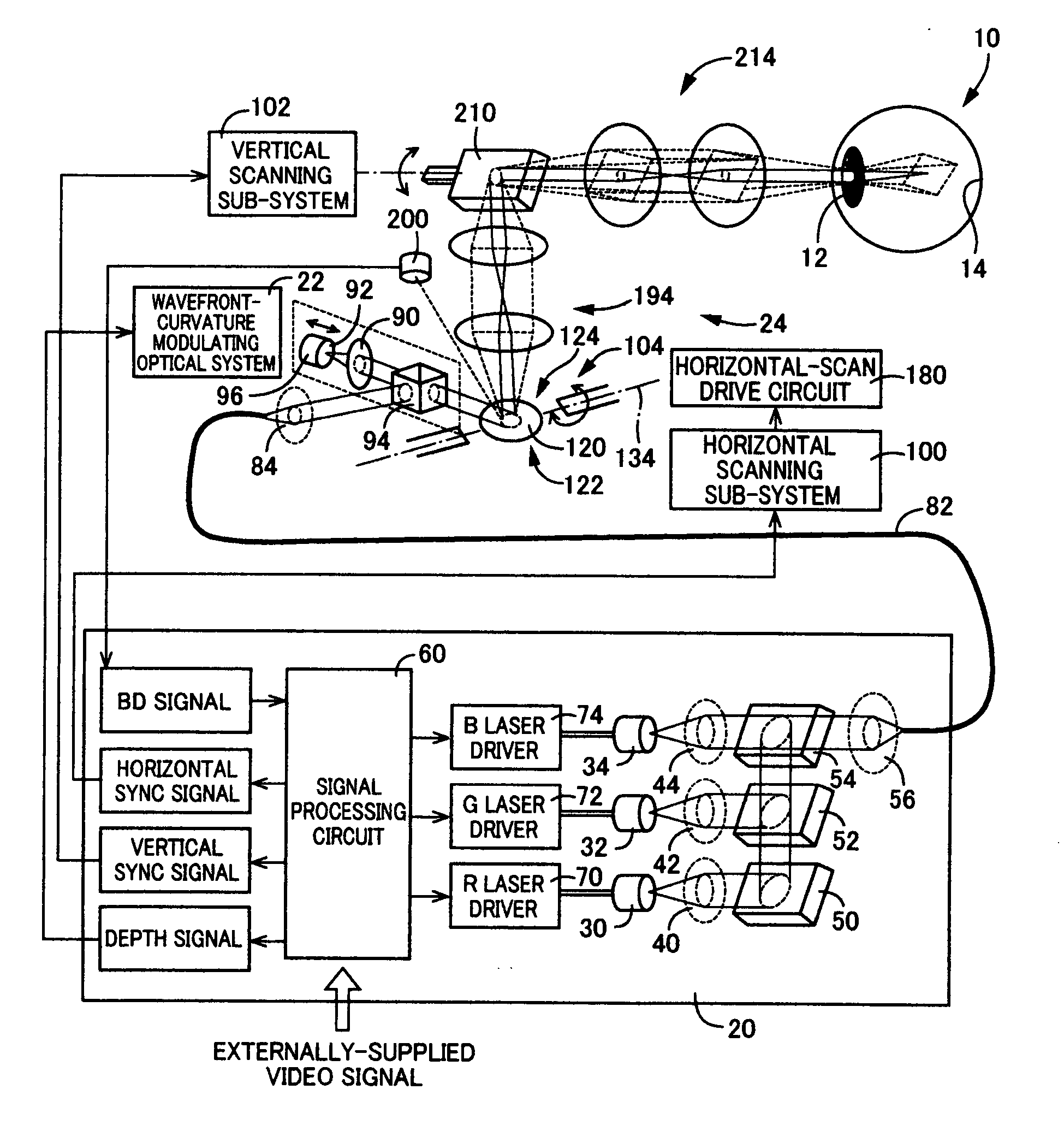
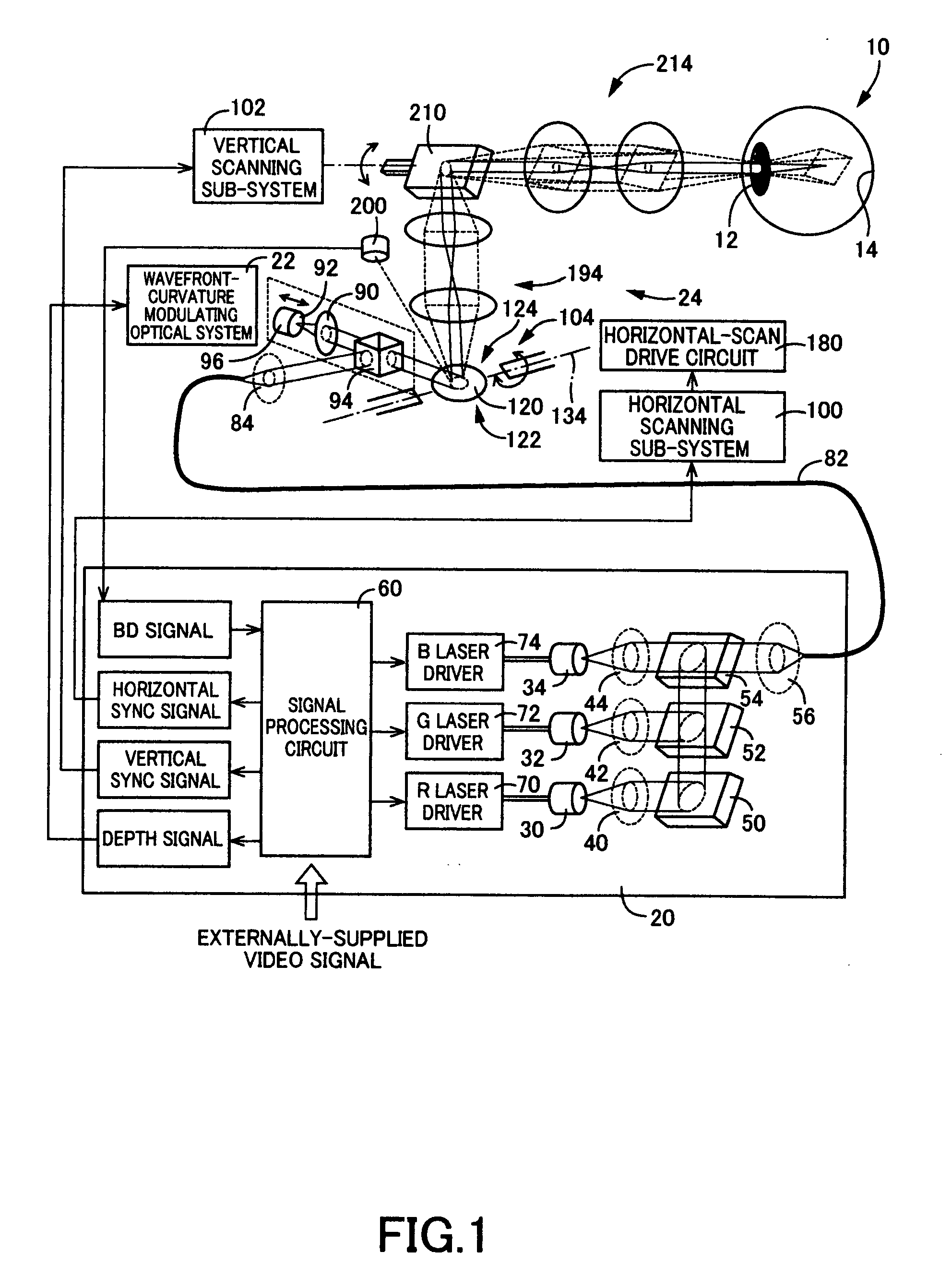
[0118] Referring to FIG. 1, there is schematically illustrated a retinal scanning display device including an optical scanner constructed in accordance with the present invention.

[0119] The retinal scanning display device (hereinafter, abbreviated as “RSD”) is adapted to direct a laser beam, through a pupil 12 of a viewer's eye 10, into an image plane on a retina 14 of the viewer, while modulating the laser beam appropriately in curvature of wavefront and intensity. The RSD is further adapted to scan the laser beam two-dimensionally on the image plane, to thereby project a desired image directly onto the retina 14.

[0120] The RSD includes a light source unit 20 and a scanning unit 24 which is disposed between the light source unit 20 and the viewer's eye 10.

[0121] In order to generate a beam of laser light of any desired color by combining sub-beams of laser light of three primary colors (i.e., red, green, and blue), the light source unit 20 includes: a laser 30 emitting a sub-beam...

second embodiment

[0193] Next, there will be described the present invention.

[0194] The present embodiment is in common in many elements to the first embodiment, while is different only in elements pertinent to the width of each segment of each integral spring 140. Therefore, only the different elements of the present embodiment will be described in greater detail below, while the common elements of the present embodiment will be omitted in detailed description by referring to the common elements using the identical reference numerals or names to those in the first embodiment.

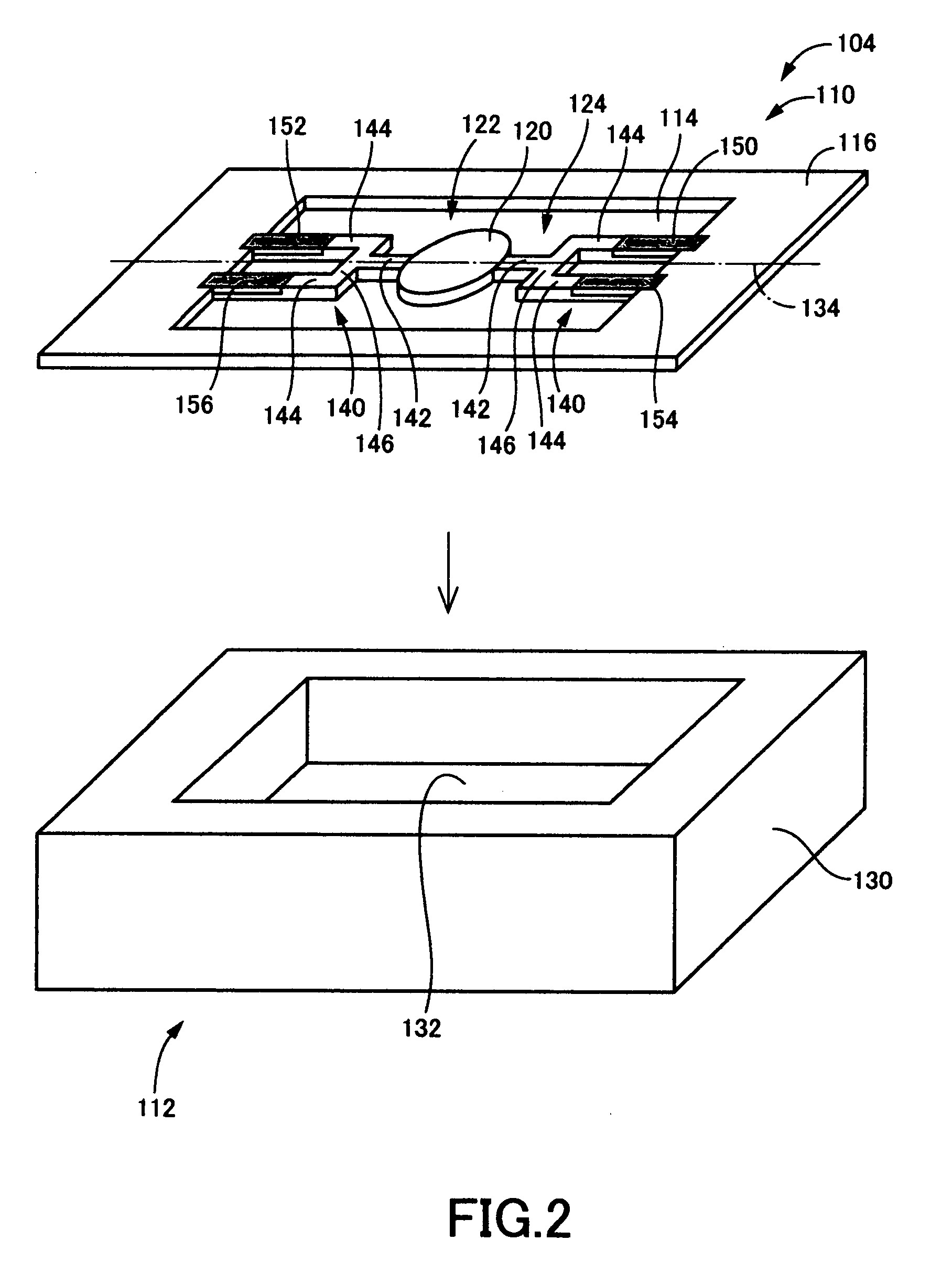
[0195] In the first embodiment, as illustrated in FIG. 7, each mirror-side leaf spring 142 has an effective width of 75 μm, and each frame-side leaf spring 144 has an effective width of 55 μm.

[0196] In contrast, in the present embodiment, each mirror-side leaf spring 142 and each frame-side leaf spring 144 have respective pre-established effective widths larger than those in the first embodiment, respectively. More specificall...

third embodiment

[0202] Next, there will be described the present invention.

[0203] The present embodiment is in common in many elements to the first embodiment, while is different only in elements pertinent to the width of each segment of each integral spring 140. Therefore, only the different elements of the present embodiment will be described in greater detail below, while the common elements of the present embodiment will be omitted in detailed description by referring to the common elements using the identical reference numerals or names to those in the first embodiment.

[0204] In the first embodiment, as illustrated in FIG. 7, each mirror-side leaf spring 142 has an effective width of 75 μm, and each frame-side leaf spring 144 has an effective width of 55 μm.

[0205] In contrast, in the present embodiment, each mirror-side leaf spring 142 and each frame-side leaf spring 144 have respective pre-established effective widths smaller than those in the first embodiment, respectively. More specifical...


PUM


Abstract

An apparatus for use in optical scanning is disclosed which vibrates at least a part of a vibrating body having a light-reflective surface, to thereby allow light, upon entry, to be reflected from the light-reflective surface in varying directions. The vibrating body includes: (a) a reflective mirror having the light-reflective surface; and (b) an integral spring extending from the reflective mirror and being excited to generate at least a torsional vibration. The vibrating body has vibrational characteristics in which whether or not a resonant frequency of the torsional vibration and a resonant frequency of a disturbing vibration are equal to each other depends upon a shape-defining parameter for defining a shape of the integral spring extending lengthwise. The shape-defining parameter is pre-set to fall within a range allowing the resonant frequency of the torsional vibration and the resonant frequency of the disturbing vibration to be different from each other.

Description

CROSS-REFERENCE TO RELATED APPLICATIONS [0001] This application is based on Japanese Patent Application No. 2004-90890 filed Mar. 26, 2004 and International Application No. PCT / JP2005 / 4040 filed Mar. 9, 2005, the contents of which are incorporated hereinto by reference. [0002] This application is a continuation application of International Application No. PCT / JP2005 / 4040 filed Mar. 9, 2005, now pending, which was published in Japanese under PCT Article 21(2).BACKGROUND OF THE INVENTION [0003] 1. Field of the Invention [0004] The invention relates to techniques for use in optical scanning, of vibrating at least a part of a vibrating body having a light-reflective surface, to thereby allow light, upon entry, to be reflected from the light-reflective surface in varying directions, and more particularly to techniques of optimizing resonant frequency characteristics of the vibrating body by optimizing the shape of the vibrating body. [0005] 2. Description of the Related Art [0006] There ...

Claims


Application Information

Patent Timeline
IPC IPC(8): G02B26/08B41J2/44B81B3/00G02B7/182G02B26/10H04N1/113
CPCB81B3/0094B81B2203/0109H04N1/113G02B26/105G02B7/1821
Inventor NISHIKAWA, YASUOASAI, NOBUAKI
Owner BROTHER KOGYO KK
Why Eureka
Try Eureka