Anti-reflection film

a technology of anti-reflection film and film body, which is applied in the direction of instruments, coatings, optics, etc., can solve the problems of increased manufacturing cost, insufficient anti-reflection effect within the visible band, so as to reduce reflectivity, enhance anti-reflection performance, and reflect poor

Inactive Publication Date: 2007-03-29
TAMRON
View PDF2 Cites 7 Cited by
  • Summary
  • Abstract
  • Description
  • Claims
  • Application Information

AI Technical Summary

Benefits of technology

[0046] The requirements of the invention, n1<n2<n3, are those to determine the well-balanced width of the reflection zone with the reflectivity, and if the requirements are not met, an imbalance of low reflectivity / narrowed reflection band width or raised reflectivity / wide reflection band width is caused. Thus, in accordance with the present invention, optimizing the refractive index, the optical film thickness (spectrometric wavelength), and the material of each component layer in combination, the resultant anti-reflection film can widen the visible light band and reduce the reflectivity therein down to less than approximately 0.5% in peak value and to less than approximately 0.2% in average.
[0047] Thus, the present invention provides an anti-reflection film of enhanced anti-reflection performance that can be applied to optical components of high refractive index so as to downsize optical products.
[0048] Furthermore, the present invention provide a cost reduced anti-reflection film of a multi-lamination structure that is reduced in number of layers and increased in thickness of the same for the purpose of facilitating the total control of the film thickness and that can be manufactured in a simplified process so as to reduce the manufacturing cost.

Problems solved by technology

The anti-reflection film disclosed in Patent Document 2 is deposited over a substrate of a high refractive index of 2.0 or even greater, and the film is of a multi-lamination structure consisting of layers as many as six in number, which results in an increased manufacturing cost.
Under such requirements of the refractive index and the film thickness, however, the anti-reflection film cannot retain its reflectivity 1% or under within a visible band from 400 nm to 700 nm when deposited over the substrate of 1.90 or greater in refractive index, which attains an insufficient anti-reflection effect within the visible band.
Under the requirements of component film thickness (i.e., spectrometric wavelength) for the queued arrangement of the substrate-0.25λ thin film-0.5λ thin film-0.25λ thin film-the air, however, the anti-reflection film applied over the substrate of 1.90 or greater in refractive index cannot retain the reflectivity 1% or below within the visible band from 400 nm to 700 nm, which attains an insufficient anti-reflection effect within the visible band.

Method used


Image

  • Anti-reflection film
  • Anti-reflection film
  • Anti-reflection film

Examples


embodiment 1

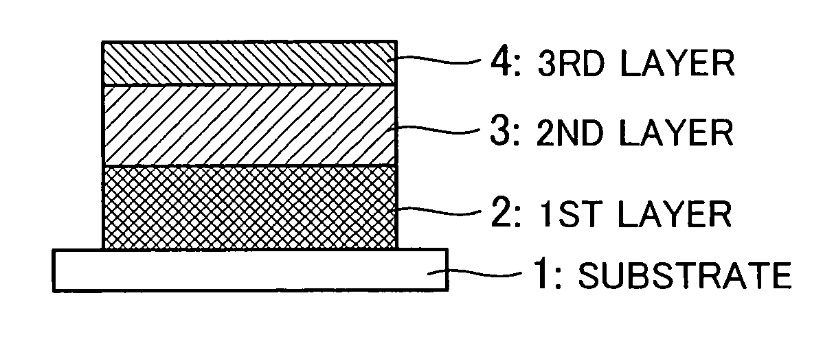
[0057] An exemplary anti-reflection film according to the present invention is 1.90 in substrate refractive index and 510 nm in spectrometric wavelength A, as detailed in the table below:

TABLE 1RefractiveSpectrometricLayer #IndexwavelengthMaterialsSubstrate1.901st Layer1.760.50 λMixtures of Y2O3, La2O3, andAl2O3,or Mixtures of ZrO2 and SiO22nd2.300.50 λNb2O5 or TiO2Layer3rd Layer1.460.25 λSiO2Air1.00

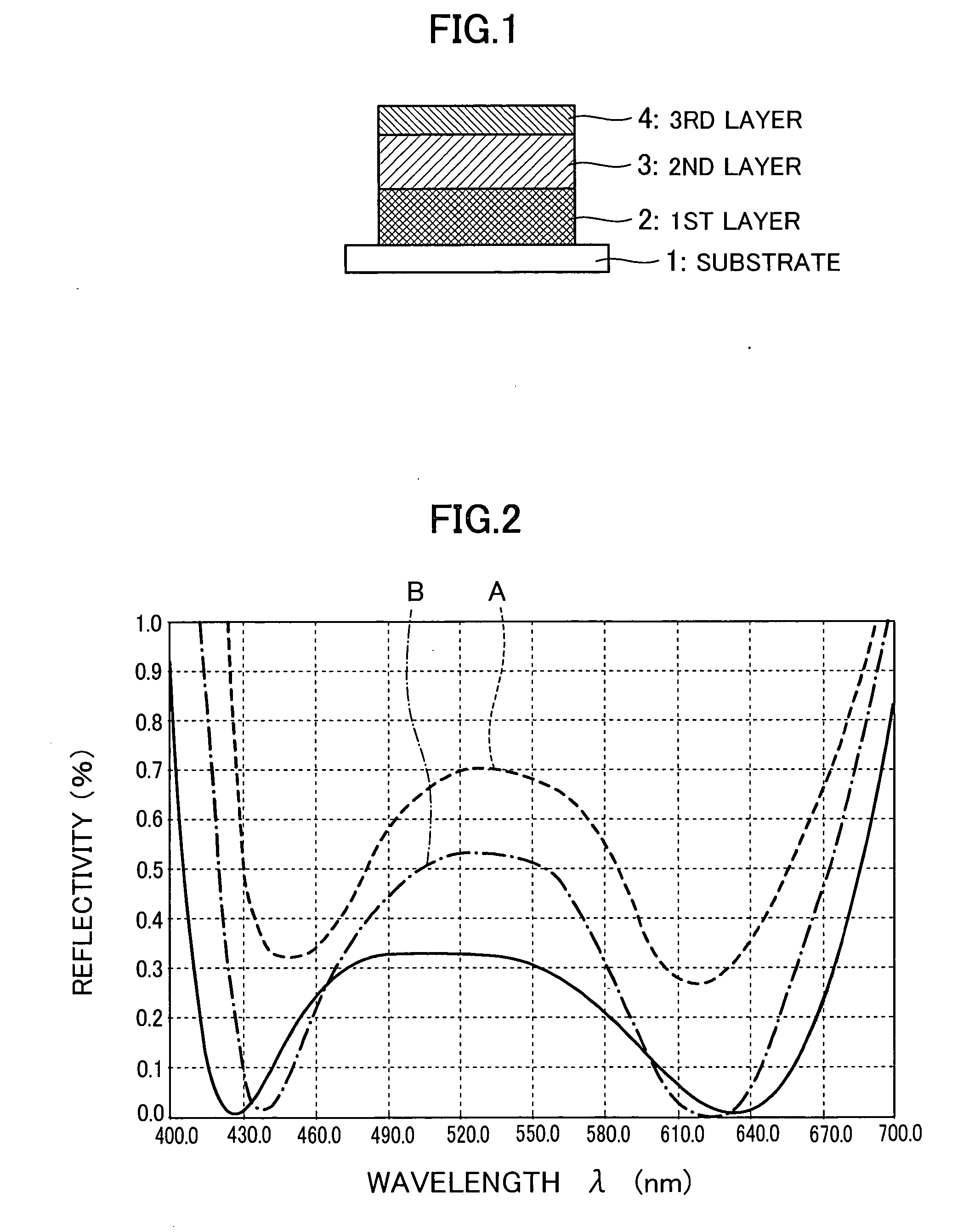
[0058]FIG. 2 shows a reflectivity of the first embodiment of the anti-reflection film in the event of an incident angle of light beam ranging from 0 to 10 degrees. As will be recognized from solid characteristic curves of the reflectivity in FIG. 2, the anti-reflection film effectively reduces the reflectivity in both shorter- and longer-wavelength zones than a peak throughout a visible light band, and it makes an inclination of the characteristic curves drastically steeper at extreme zones of further shorter and longer wavelengths. In this way, the reflectivity can be retained down to...

embodiment 2

[0064] Another or a second embodiment of the present invention is 2.00 in substrate refractive index and 510 nm in spectrometric wavelength λ, as detailed in the table below:

TABLE 2RefractiveSpectrometricLayer #IndexwavelengthMaterialsSubstrate2.00S-LAH79 (Available fromOhara, Inc.)1st Layer1.760.50 λMixtures of Y2O3, La2O3, andAl2O3,or Mixtures of ZrO2 and SiO22nd2.350.50 λNb2O5 or TiO2Layer3rd Layer1.460.25 λSiO2Air1.00

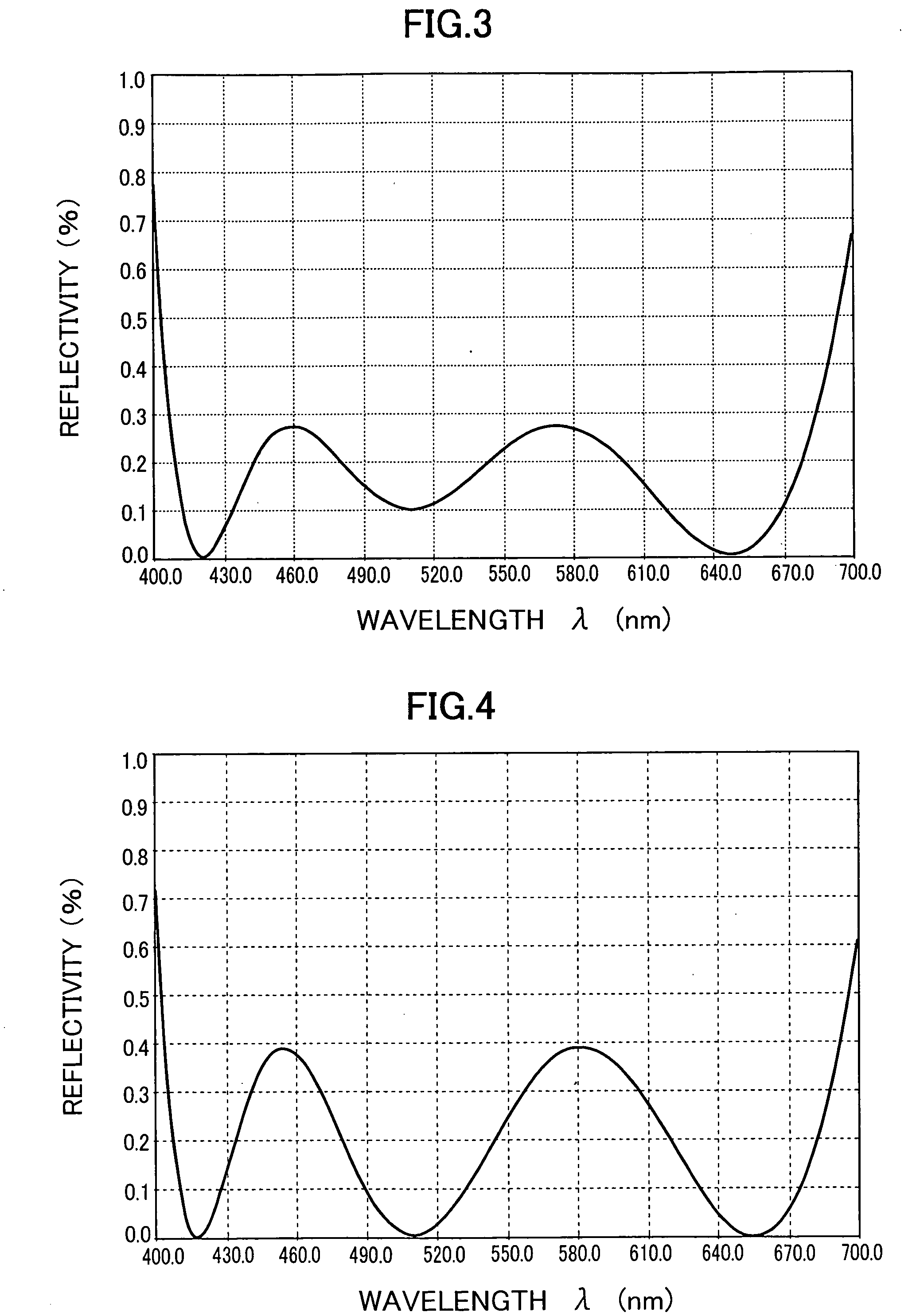
[0065]FIG. 3 shows a reflectivity of the second embodiment of the anti-reflection film in the event of the incident angle of light beam ranging from 0 to 10 degrees. This embodiment of the anti-reflection film has its substrate refractive index raised up to 2.00 and the second-layer refractive index up to 2.35, respectively. As can be seen from a solid characteristic curve of the reflectivity in FIG. 3, there are relatively moderately pointed two peaks throughout the entire width of the visible light transmitting band where a reflectivity level of both the peaks i...

embodiment 3

[0066] Another or a third embodiment of the anti-reflection film according to the present invention is 2.10 in substrate refractive index and 510 nm in spectrometric wavelength λ, as detailed in the table below:

TABLE 3RefractiveSpectrometricLayer #IndexwavelengthMaterialsSubstrate2.101st Layer1.760.50 λMixtures of Y2O3, La2O3, andAl2O3,or Mixtures of ZrO2 and SiO22nd2.400.50 λTiO2Layer3rd Layer1.460.25 λSiO2Air1.00

[0067]FIG. 4 shows a reflectivity of the third embodiment of the anti-reflection film in the event of the incident angle of light beam ranging from 0 to 10 degrees. This embodiment of the anti-reflection film is 2.10 in substrate refractive index and 2.40 in second-layer refractive index, and the material of the second layer is restricted to TiO2. The third embodiment of the anti-reflection film exhibits, in comparison with the second embodiment, a property expressed by the very similar characteristic curve where there are two peaks throughout the visible light band; mor...


PUM

PropertyMeasurementUnit
refractive indexaaaaaaaaaa
refractive index n3aaaaaaaaaa
reflectivityaaaaaaaaaa

Abstract

The present invention is dedicated to a cost reduced anti-reflection film of a multi-lamination structure that is reduced in number of layers and increased in thickness of the same for the purpose of facilitating the total control of the film thickness and that can be manufactured in a simplified process so as to reduce the manufacturing cost. Three component layers are deposited one over another on a substrate ranging from 1.90≦ns≦2.10 in refractive index at an arbitrary design basis wavelength within a wavelength range in and near visible band, and these layers exhibit optical properties as in the following table: Refractive Index ‘n’Optical Film thickness ‘nd’1st Layer1.54 ≦ n1 ≦ 2.000.465 λ≦ n1d1 ≦ 0.575 λ2nd Layer1.95 ≦ n2 ≦ 2.630.490 λ≦ n2d2 ≦ 0.508 λ3rd Layer1.35 ≦ n3 ≦ 1.550.245 λ≦ n3d3 ≦ 0.255 λ

Description

FIELD OF THE INVENTION [0001] The present invention relates to an anti-reflection film that has a substrate ranging from 1.9 to 2.1 in refractive index and is applied to optical components. [0002] Downsizing devices and apparatuses is an endless strong demand in the market, and therefore, downsizing optical components built in the devices and apparatuses is an important goal in optical engineering design. To fabricate compact optical components, it is required to employ optical materials of higher refractive index, and an additional requirement is a cost reduced anti-reflection film of improved anti-reflection performance for such optical materials of the enhanced refractive index. BACKGROUND ART [0003] An anti-reflection film proposed in the art is of a multi-lamination structure where seven component layers are deposited one over another on a substrate ranging from 1.4 to 1.9 in refractive index at an arbitrary design basis wavelength within a wavelength range near visible band (s...

Claims


Application Information

Patent Timeline
Patent Type & Authority Applications(United States)
IPC IPC(8): G02B5/28G02B1/11
CPCG02B1/115
Inventor WATANABE, YASUHISASHIRAI, YOSHIYUKI
Owner TAMRON
Why Eureka
Try Eureka