
Sonic instrumentation apparatus and method for cement bond logging

Active Publication Date: 2007-03-29
PROBE TECH SERVICES
View PDF18 Cites 19 Cited by
  • Summary
  • Abstract
  • Description
  • Claims
  • Application Information

AI Technical Summary

Benefits of technology

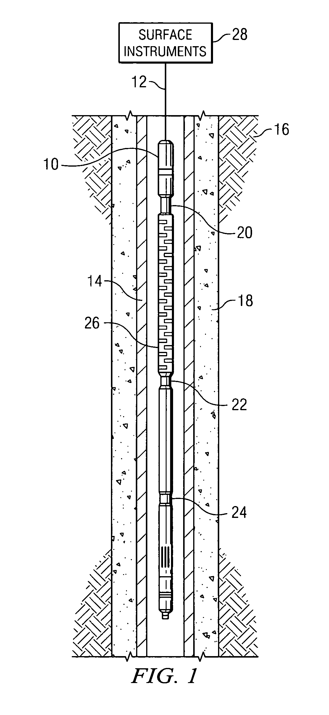
[0015] In another aspect of the invention, a method is provided for processing electrical signals produced by a longitudinally segmented acoustic receiving transducer in a logging tool, wherein synchronizing pulses are issued to the longitudinally segmented receiving transducer at a predetermined repetition rate and wherein the transducer output signals are processed at high speed in digital signal processing circuitry to provide signals normalized in real time according to built-in calibration factors and having a high signal-to-noise ratio and a high degree of clarity, thereby extending the usable range of data that is sent to the surface instrumentation.

Problems solved by technology

Operation of the cement bond logging tools must occur in some highly challenging environments.
These environmental conditions impose severe stresses upon the electronics and the mechanical structures of the instrument.
Further, conventional PZT elements typically function most efficiently at or near resonance, to avoid the effects of spurious vibrations that can interfere with the intended signals, thus limiting their usefulness as transducers.
In addition, operation of the crystal at only one frequency limits the utility of the transducers to the use of only the one frequency.
Other aspects of prior art logging tools that limit their utility and efficiency include the following.
The processing of the data signals tends to be relatively slow in comparison to the amount of data that can be provided by the transducer.
The result is that the data only represents a small and often insufficient sampling of the cement bond as the tool is pulled upward.
Moreover, because of the need to limit the upward rate, in feet-per-minute, that the tool is pulled toward the surface so that an adequate amount of data is obtained, substantial time is required to produce a complete cement bond log.
Especially time consuming is the time needed to calibrate the instrument for the particular logging operation.
When the wire line is used to transmit analog signals to the surface instrumentation, this complex impedance and the length of the wire line must be compensated and usually involves tedious adjustments of the gain of each of the eight or more analog preamplifiers in the logging tool.
Further, the particular adjustments are usually applicable only for the conditions existing at the time these adjustments are made because they are subject to being invalid as the logging tool is moved to another location, used with another surface vehicle, the temperature or other conditions in the well casing change, etc.

Method used


Image

  • Sonic instrumentation apparatus and method for cement bond logging
  • Sonic instrumentation apparatus and method for cement bond logging
  • Sonic instrumentation apparatus and method for cement bond logging

Examples


Embodiment Construction

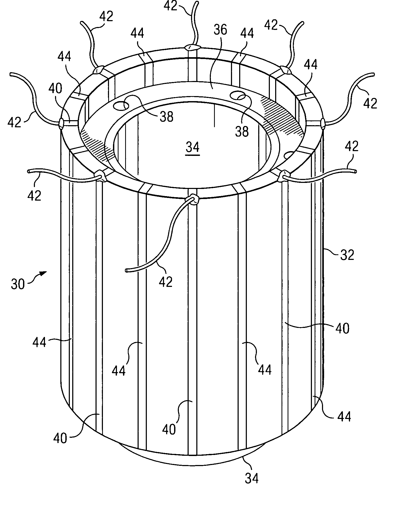
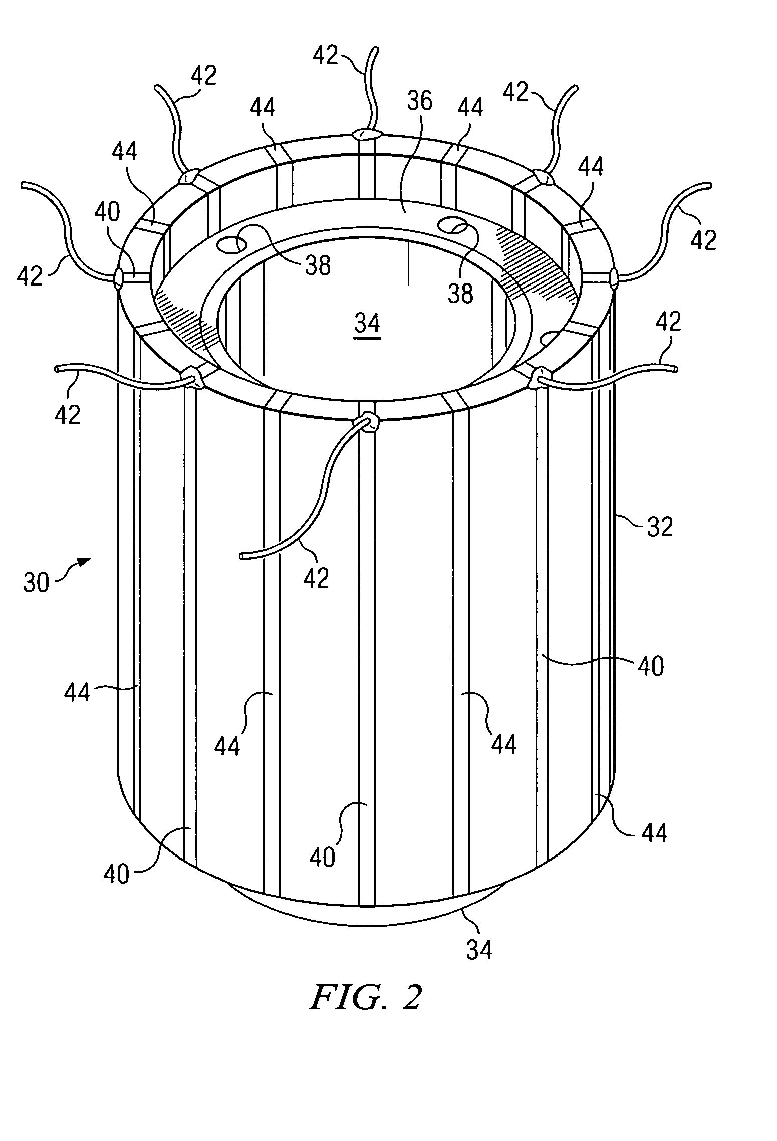
[0034] For the purposes of this detailed description several terms are defined as follows. The basic geometric form of many transducers used in down-hole logging tools is a cylinder having a longitudinal axis defined through the center of the cylinder and a radius with respect to this axis that defines the outer and inner surfaces. Elements of the transducers are typically disposed in or on the outer portions of the cylindrical form. In the prior art, it is known to arrange these elements circumferentially or azimuthally around the cylindrical form, often with equal spacings and, correspondingly, equal radial angles, between the adjacent elements. In the present description, these elements will be identified as radial sectors of the transducer.

[0035] In the present invention to be described, the transducer elements may be subdivided and arranged in the direction of the longitudinal axis. The individual subdivisions, which may be placed adjacent to each other or separated by a thin ...


PUM


Abstract

A longitudinally segmented acoustic transducer for a cement bond logging (CBL) tool having a plurality of adjoining PZT ring-like segments driven synchronously in parallel by one or more pulses and caused to vibrate in an anti-resonant mode, substantially below the resonant frequency of an individual segment when used in a transmitting application. When used in a receiving application, each of the plurality of transducer rings are caused to vibrate by acoustic signals detected by the transducer array, also in an anti-resonant mode. High speed digital signal processing enables on-depth, high quality data for all azimuths at each depth to be obtained, processed, normalized and either sent to the surface in real time for each 20 Hz firing cycle, as the CBL tool is pulled toward the surface, or stored in a memory module in digital form for later retrieval. Built-in calibration factors used for normalizing the output signals to the operating conditions of use may be accessed at any time.

Description

CROSS REFERENCE TO RELATED APPLICATIONS [0001] The present U.S. patent application is related to co-pending U.S. patent application entitled METHOD FOR PROCESSING SIGNALS IN A CEMENT BOND LOGGING TOOL, and also to co-pending U.S. patent application entitled METHOD FOR NORMALIZING SIGNALS IN A CEMENT BOND LOGGING TOOL, both filed by the same applicant on the same date as the present application.BACKGROUND OF THE INVENTION [0002] 1. Field of the Invention [0003] The present invention generally relates to instrumentation for logging conditions in down hole formations and, more particularly to transducer design and uses thereof in acoustic logging instrumentation. The acoustic transducer designs disclosed herein may be adapted to a variety of applications, including, for example, cement bond logging. [0004] 2. Background of the Invention and Description of the Prior Art [0005] The use of piezoelectric materials such as a polycrystaline form of lead titanate or lead zirconate titanate, s...

Claims


Application Information

Patent Timeline
IPC IPC(8): H04R17/00
CPCB06B1/0633H04R1/00E21B47/0005E21B47/005
Inventor HURST, BRIANBECKMAN, MARVIN W.
Owner PROBE TECH SERVICES
Learn More