Power supply unit and method for cooling battery contained therein

a power supply unit and battery technology, applied in secondary cell servicing/maintenance, cell components, electrochemical generators, etc., can solve the problems of generating a higher temperature, difficult or impossible to uniformly cool each individual battery module, and reducing cooling performance, so as to achieve efficient cooling, minimize temperature differences, and improve cooling efficiency

Inactive Publication Date: 2007-03-29
SANYO ELECTRIC CO LTD
View PDF4 Cites 56 Cited by
  • Summary
  • Abstract
  • Description
  • Claims
  • Application Information

AI Technical Summary

Benefits of technology

[0009] Unexamined Japanese Patent Application No. 1999-329518, on the other hand, describes a power supply unit which contains battery modules in three or more tiers within a holder case. In that power supply unit, a plurality of battery modules, being postured in parallel and separated along the direction of cooling air, are contained within the holder case in a multi-tier manner. With this power supply unit, the cooling air is forcibly blown in between the battery modules to cool the battery modules. Disadvantageously, however, such a cooling structure will make a cooling performance less effective for a battery module in the downstream than for battery module in the upstream, thus generating a higher temperature. To overcome such a shortcoming, the holder case has an air turbulence accelerator, such as a dummy battery unit, provided in the uppermost stream, so that a stream of cooling air coming into the holder case may be disturbed to allow the battery module in the upstream to be efficiently cooled. Also, the holder case has an auxiliary air intake provided intermediate of a cooling air path, which is so designed as to allow the cooling air in, and thus a cooling efficiency may be increased for a battery in the downstream.
[0010] In the above-described power supply unit, a cooling effect for the battery module in the downstream can certainly be enhanced by means of the air turbulence or by the cooling air which is taken in intermediately. With such structure, however, it is impossible to cool a total number of battery modules down to a uniform temperature.
[0011] The present invention has been made in order to solve such disadvantages. It is, therefore, an important object of the present invention to provide a power supply unit which can reduce a temperature difference among a plurality of batteries contained within a holder case in an upper-and-lower, multi-tier manner, so that a uniform cooling performance may be made available for upper and lower batteries.
[0016] The above-described power supply unit and battery cooling method carry the advantage that the temperature difference between the batteries contained in an upper-and-lower, multi-tier manner within the holder case, especially the temperature difference between the top and bottom batteries, can be reduced to minimum so that the upper and lower batteries are uniformly cooled. This is made possible because the fan is switched into or out of operation so that the temperature difference is minimized through switching the fan for the upper or lower batteries to be efficiently cooled. While the fan is in operation, the cooling air is blown from top to bottom to efficiently perform a cooling operation for the upper battery. While the fan is not in operation, natural convection caused by natural heat radiation works to efficiently cool the lower battery. Thus, when the temperature is elevated in the lower battery while the fan is in operation, the fan stops operation to cool the lower battery more efficiently than the upper battery, thus minimizing the temperature difference. When the temperature is elevated in the upper battery while the fan is not in operation, the fan starts operation to cool the upper battery more efficiently than the lower battery, thus minimizing the temperature difference.

Problems solved by technology

However, when battery modules are to be contained in three or more tiers within the holder case for reducing a total installation area, it becomes difficult or impossible to uniformly cool each individual battery module.
Disadvantageously, however, such a cooling structure will make a cooling performance less effective for a battery module in the downstream than for battery module in the upstream, thus generating a higher temperature.
With such structure, however, it is impossible to cool a total number of battery modules down to a uniform temperature.

Method used


Image

  • Power supply unit and method for cooling battery contained therein
  • Power supply unit and method for cooling battery contained therein
  • Power supply unit and method for cooling battery contained therein

Examples


Embodiment Construction

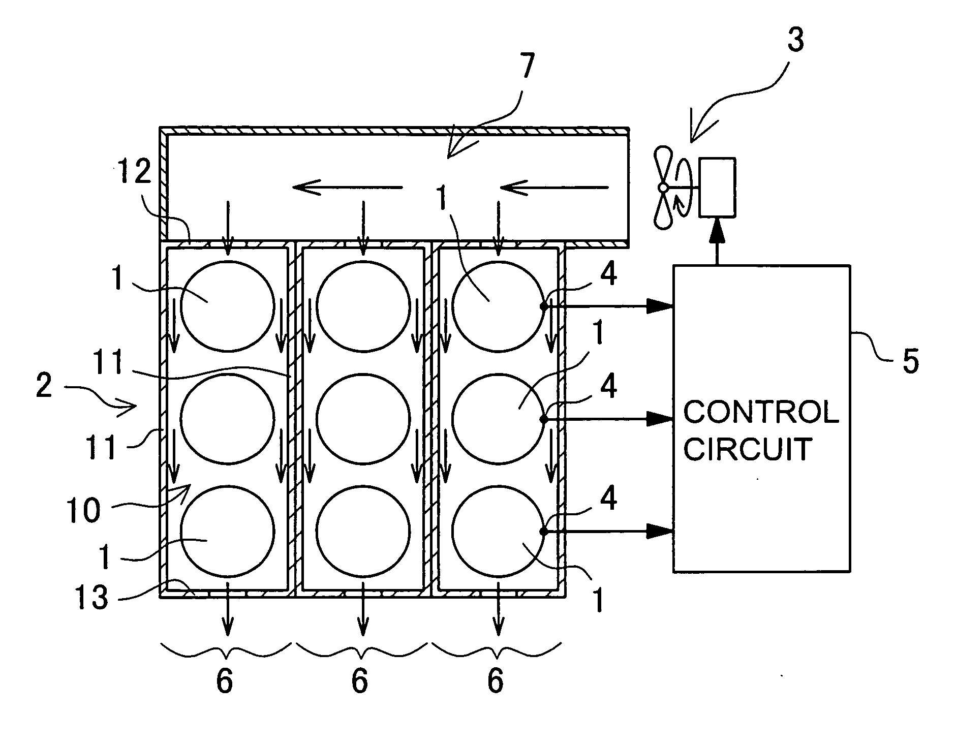
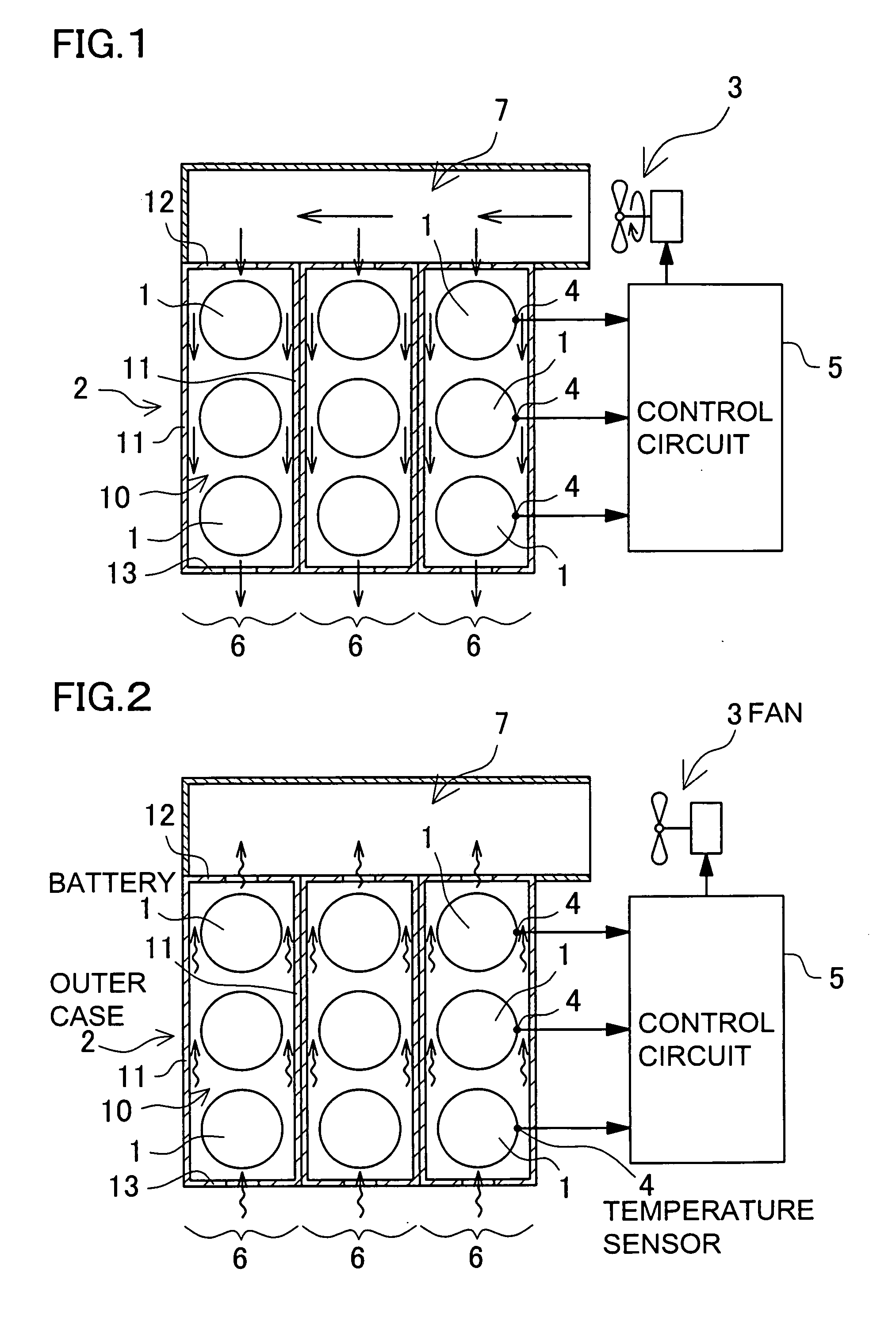
[0024] A power supply unit shown in FIGS. 1 and 2 includes a plurality of batteries 1 disposed up and down within a case 2, a fan 3 for forcibly blowing cooling air from top to bottom within the case 2 to cool the batteries 1, a temperature sensor 4 for detecting a temperature of the batteries 1 contained within the case 2, and a control circuit 5 for controlling operation of the fan 3 by means of a signal fed out of the temperature sensor 4.

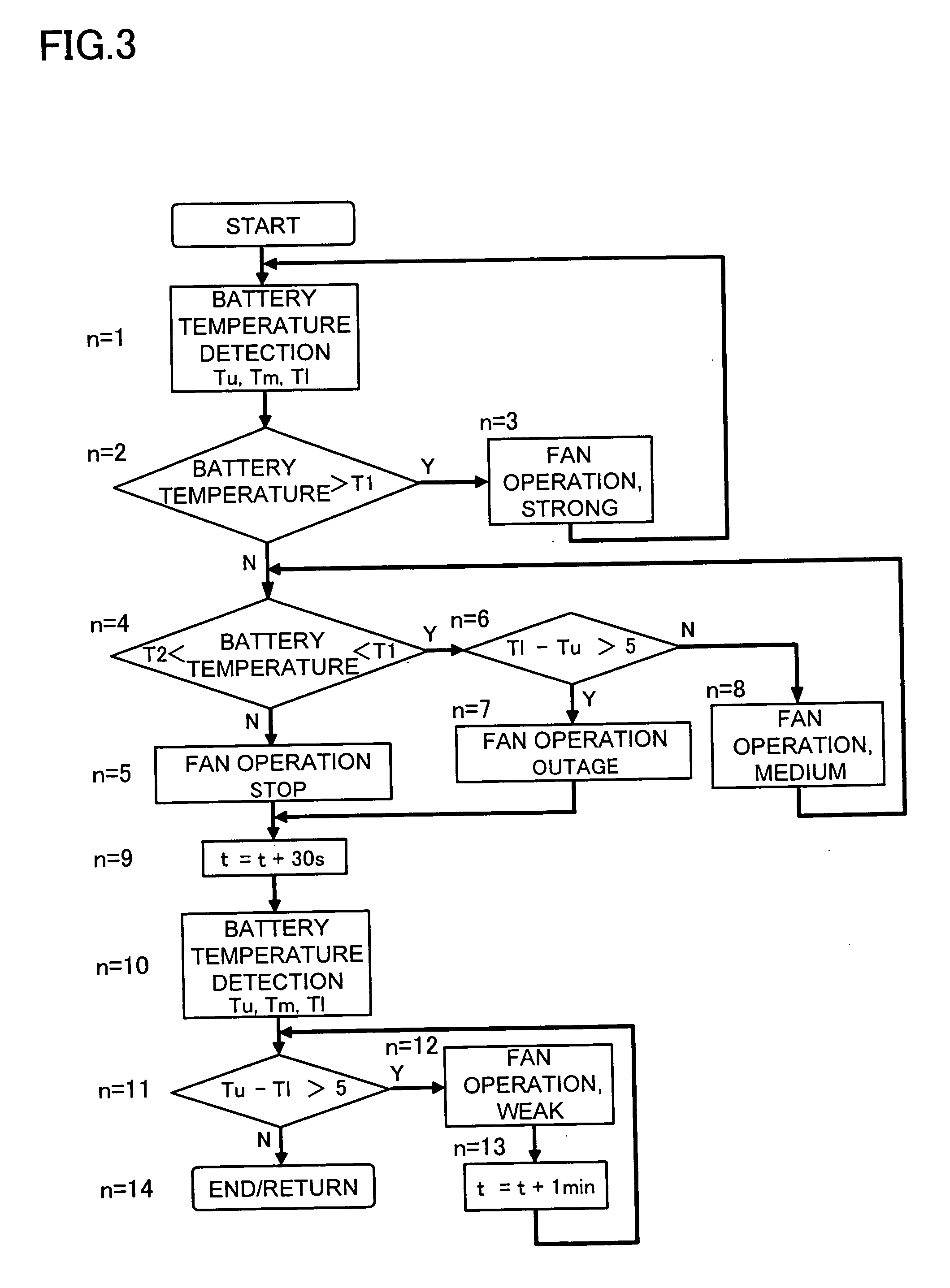
[0025] With the above-described power supply unit, when a battery temperature reaches above a set value of temperature, the control circuit 5 starts operating the fan 3 to cool the batteries 1, and when a battery temperature is below the set value of temperature, the circuit 5 stops operating the fan 3 to retain the batteries 1 at a predetermined temperature.

[0026] When the fan 3 is in operation, as shown in FIG. 1, the power supply unit forcibly blows the cooling air from top to bottom within the case 2 so as to cool the batteries 1. When the...


PUM

PropertyMeasurementUnit
temperatureaaaaaaaaaa

Abstract

A method for cooling a battery is disclosed, in which a power supply unit includes a plurality of batteries disposed up and down (in a multi-tier manner) within a case, a fan for cooling the batteries by forcibly blowing cooling air from top to bottom within the case, a temperature sensor for detecting temperatures of the batteries, and a control circuit for controlling operation of the fan by means of a signal fed out of the temperature sensor. In the battery cooling method, when a battery temperature difference between the upper battery and the lower battery reaches above a set value as detected by the temperature sensor while the fan is in operation, the control circuit stops operation of the fan to cool the batteries through natural heat radiation.

Description

BACKGROUND OF THE INVENTION [0001] 1. Field of the Invention [0002] The present invention relates to a power supply unit which self-contains a plurality of batteries within an outer case and a method for cooling the batteries contained in the power supply unit, and particularly to a power supply unit and a method in which the batteries disposed in an upper-and-lower, multi-tier manner are cooled down to a uniform temperature. [0003] 2. Description of the Related Art [0004] power supply unit, which self-contains a plurality of batteries within a case, is primarily used as a power source for driving a motor mounted to an electric motor vehicle such as an electric car and a hybrid car, the latter being designed to travel optionally with an internal combustion engine or with an electric motor. A power supply unit used for this kind of application is designed to have a higher output voltage so that a large electricity may be supplied to a motor which requires a high power. In order to sa...

Claims


Application Information

Patent Timeline
Patent Type & Authority Applications(United States)
IPC IPC(8): H01M10/50B60K11/06H01M10/60H01M10/613H01M10/617H01M10/625H01M10/633H01M10/6556H01M10/6562H01M10/6563H01M50/213H01M50/289
CPCH01M2/1077H01M10/4207H01M10/5004H01M10/5008H01M10/5016H01M10/5073H01M10/503H01M10/5046H01M10/5059H01M10/5067H01M10/5022H01M10/625H01M10/633H01M10/6563H01M10/6551H01M10/6557H01M10/643H01M10/617H01M10/6566H01M10/613Y02E60/10H01M50/213H01M50/289H01M50/20H01M50/10
Inventor SHIMIZU, HIDEO
Owner SANYO ELECTRIC CO LTD
Why Eureka
Try Eureka