
Intraluminal medical device with nested interlocking segments

a medical device and interlocking technology, applied in the field of intraluminal medical devices, can solve the problems of balloon stents often impractical for use in some vessels, undetectable folding and closing of lumens, and affecting so as to increase the stability of the stent and increase the vascular support

Active Publication Date: 2007-03-29
CARDINAL HEALTH SWITZERLAND 515 GMBH
View PDF6 Cites 51 Cited by
  • Summary
  • Abstract
  • Description
  • Claims
  • Application Information

AI Technical Summary

Benefits of technology

[0020] Various aspects of the systems and methods of the invention comprise an intraluminal medical device having nested interlocking segments that remain interlocked when delivered to an intended treatment site. The medical device is preferably a stent wherein nested interlocked segments provide increased stability of the stent during delivery thereof to the intended treatment site. Ideally the stent further provides increased vascular support to a vessel in which the stent is emplaced.
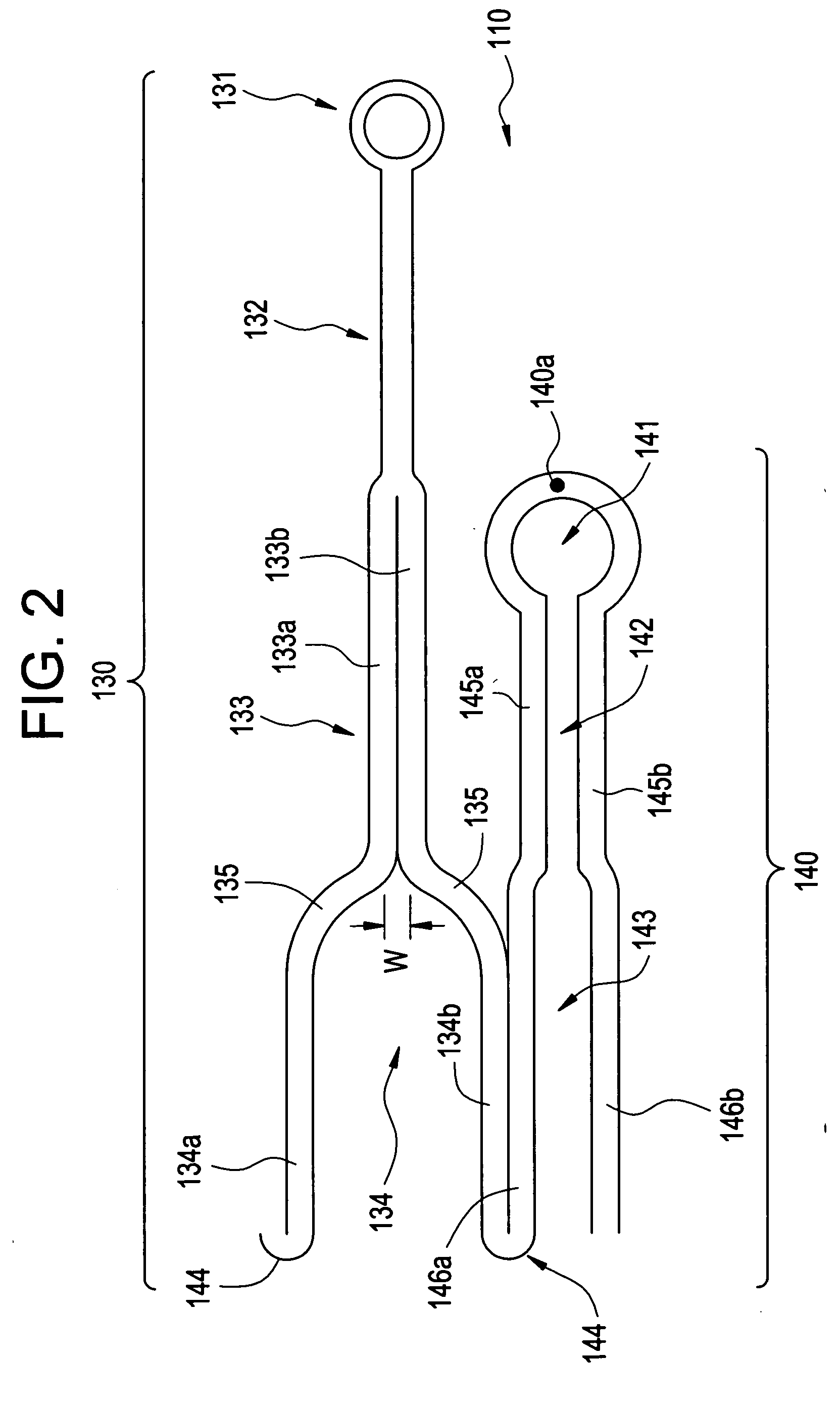
[0021] In a preferred embodiment, the stent comprises multiple, self-expanding segments axially adjacent one another. Each segment is further comprised of a series of repeating cells radially and circumferentially aligned with one another to comprise the segments and aligned with axially adjacent cells to comprise the stent. Each cell further comprises a protrusion and at least one receptacle radially and circumferentially adjacent one another. A predetermined number of protrusions from cells in each segment is received by a corresponding receptacle in an axially adjacent segment. The stent thus comprises at least one axially interconnected protrusion and receptacle, although it is preferable to have more than one interconnected protrusion and receptacle. The protrusions can include radiopaque markers to enhance fluoroscopic, or other, visualization.
[0022] In some embodiments, the at least one protrusion from cells of each segment nests within the corresponding receptacle of an axially adjacent segment during delivery of the stent to the intended treatment site. The protrusions uncouple from the respective receptacles upon expansion of the stent when full deployment is effected. In other embodiments, the protrusions remains engaged with the respective receptacles as and after deployment is effected. By lengthening the interlocked components of the stent segments, the coupling of the interlocked components is maintained longer, thereby minimizing undesirable tipping or other rotation of the stent during delivery and minimizing the likelihood of undesirable propelling of the segments during delivery. Further, to the extent that the nesting of the interlocked components exists after deployment of the stent, such nesting enhances vascular support to the vessel even where uncoupling of the protrusions and receptacles occurs.

Problems solved by technology

A dissection “flap” of underlying tissue can occur, however, which can undesirably fold into and close off the lumen.
Such balloon stents are often impractical for use in some vessels, such as the carotid artery.
Thus, emplacement of a balloon expandable stent in such a vessel poses severy injury risks to a patient through even day-to-day activities, particularly where a force to the patient's neck could result in collapse of the stent within the vessel.
Braided stents have many disadvantages, however, including insufficient radial strength to effectively hold open a diseased vessel.
In addition, the plurality of wires or fibers comprising a braided stent become dangerous if separated from the body of the stent as they could pierce through the vessel.
Methods of using the shape memory characteristics of these alloys in medical devices intended to be placed within a patient's body present operational difficulties.
For example, with shape memory alloys having a stable martensite temperature below body temperature, it is frequently difficult to maintain the temperature of the medical device containing such an alloy sufficiently below body temperature to prevent the transformation of the martensite phase to the austenite phase when the device was being inserted into a patient's body.
In stent designs having periodically positioned bridges, for example, the resulting gaps between unconnected loops may be disadvantageous.
These forces are transmitted axially through the stent by the connecting bridges and may cause undesirable buckling or compression of the adjacent loops in the areas where the loops are not connected by bridges.
The attached markers tend to increase the profile of the stent, and can dislodge from the stent or otherwise compromise the performance of the stent.
The axial and radial expansion of the otherwise constrained stent, and the bending of the stent, that occurs during delivery and deployment, often renders conventional interconnected stents susceptible to fatigue fractures.
Even where connected strut segments have been designed to disconnect upon deployment in order to minimize the occurrence of fatigue fractures, such as in co-pending U.S. patent application Ser. No. 10 / 687,143, filed Oct. 18, 2003, of common assignment herewith, such stents can prove unstable and susceptible to tipping or rotation within a vessel, particularly during delivery.
Moreover, where the L / D ratio, i.e., the ratio of a expanded strut length L to an expanded diameter D, is greater than one due to a length L greater than a diameter D, for example, then the stent tends to be weaker and intended vessel support tends to be compromised.
The weaker stent can be even more susceptible to fatigue fractures or other strain induced irregularities, while the longer stent segment lengths L result in larger gaps between structural components of the stent, which compromises vessel support.
On the other hand, where the L / D ratio approaches zero, particularly where L approaches zero, then uniform and predictable positioning of the various segments comprising a stent is compromised.
As a result, unpredictable propelling of the segments from the delivery device can occur.

Method used


Image

  • Intraluminal medical device with nested interlocking segments
  • Intraluminal medical device with nested interlocking segments
  • Intraluminal medical device with nested interlocking segments

Examples


Embodiment Construction

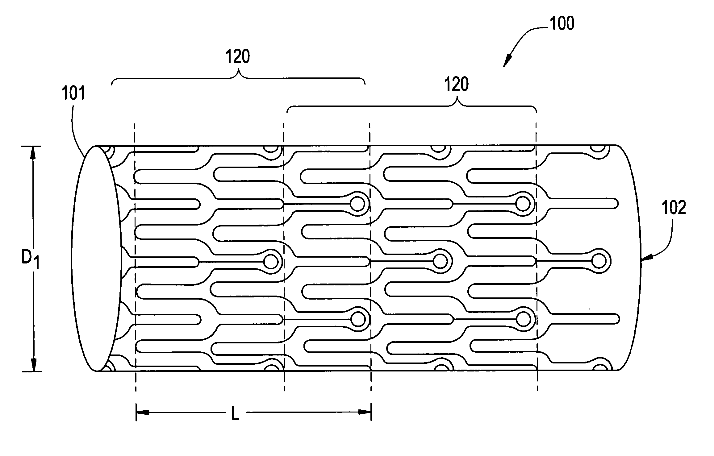
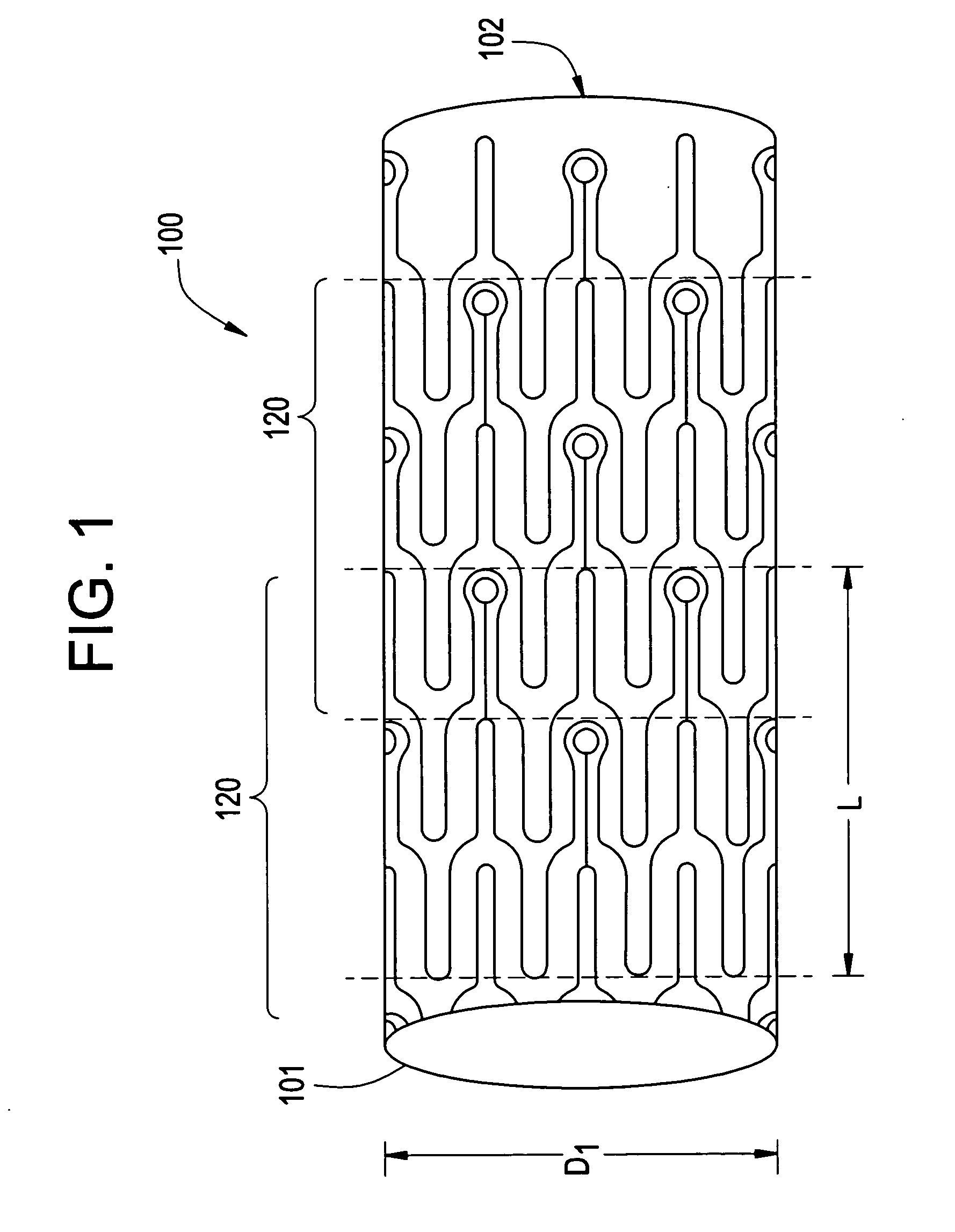
[0048]FIG. 1 illustrates a schematic view of a stent 100 according to one embodiment of the invention. Unless otherwise indicated, the length L is the length of a segment, for example, segment 120, of the stent 100 in its expanded state, whereas diameter D is the diameter of the stent 100, wherein D1 is the diameter of the stent in its constrained state and D2 is the diameter of the stent in its expanded state. As referenced herein, an L / D ratio refers to the ratio of the length L of a segment of the stent to a diameter D of the stent in its expanded state. Although the stent can be made from any of several known shape memory or superelastic biocompatible materials, as should be readily appreciated by the artisan, the stent 100 described herein is preferably comprised of a superelastic alloy such as Nitinol. Most preferably, the stent 100 is made from an alloy comprising about 50.0 per cent (as used herein these percentages refer to weight percentages) Ni to about 60 percent Ni, and...


PUM


Abstract

An intraluminal medical device having nested interlocking axially adjacent segments that remain interlocked during delivery to an intended treatment site. The medical device is preferably a stent in which the nested interlocked axially adjacent segments provide increased control and stability of the stent during delivery and increased vessel support when full deployment is effected. The stent may be a self-expanding stent or a balloon expandable stent. In either case, a series of repeating cells comprise a segment. Each cell comprises a protrusion and a radially and circumferentially adjacent receptacle. The protrusion from at least one cell in a segment interlocks with the receptacle of an axially adjacent segment to form the stent. The protrusions remain coupled with a corresponding receptacle during delivery of the stent to the intended treatment site, and can remain engaged thereafter, or can disengage from the corresponding receptacle after full deployment of the stent is effected. An LID ratio of the expanded length of the stent segment relative to the expanded diameter of the stent is preferably greater than one to enhance stent delivery and maximize fatigue durability of the structure. Radiaopaque markers may be inserted within, integral therewith, or coated thereon ends of the protrusions.

Description

BACKGROUND OF THE INVENTION [0001] 1. Field of the Invention [0002] The invention relates to intraluminal medical devices. More particularly, the invention relates to stents having nested interlocking segments that provide increased stability by remaining interlocked during delivery, and that provide enhanced vascular support, while maximizing fatigue durability of the implant. [0003] 2. Related Art [0004] Percutaneous transluminal angioplasty (PTA) is a therapeutic medical procedure used to increase blood flow through an artery. In this procedure, an angioplasty balloon is inflated within the stenosed vessel, or body passageway, in order to shear and disrupt the wall components of the vessel to obtain an enlarged lumen. A dissection “flap” of underlying tissue can occur, however, which can undesirably fold into and close off the lumen. Immediate corrective surgery becomes necessary as a result. [0005] More recently, transluminal prosthesis, such as stents, have been used for implan...

Claims


Application Information

Patent Timeline
IPC IPC(8): A61F2/06A61F2/82
CPCA61F2/91A61F2/915A61F2/95A61F2002/828A61F2002/91516A61F2250/006A61F2002/91533A61F2002/9155A61F2002/91591A61F2002/9665A61F2002/91525
Inventor BONSIGNORE, CRAIG
Owner CARDINAL HEALTH SWITZERLAND 515 GMBH
Learn More