Deflecting electromagnet and ion beam irradiating apparatus

a technology of ion beam and electromagnet, which is applied in the direction of magnetic discharge control, separation process, instruments, etc., can solve the problems of difficult supply from the outside, difficult to efficiently transport ion beam, complex structure, etc., and achieves efficient neutralization, simplified power source configuration, and wide space charge of ion beam

Inactive Publication Date: 2007-04-05
NISSIN ION EQUIP CO LTD
View PDF15 Cites 10 Cited by
  • Summary
  • Abstract
  • Description
  • Claims
  • Application Information

AI Technical Summary

Benefits of technology

[0063] The ninth aspect of the invention can attain a further effect that the configuration of the power source can be simplified.
[0064] According to the tenth aspect of the invention, the distances between the first and second pairs of correcting electrodes and the third and fourth pairs of correcting electrodes can be prolonged, and the reciprocal confinement length of electrons along the ion beam passing direction can be made long. Therefore, a region where space charges of the ion beam are neutralized can be widened. As a result, space charges of the ion beam can be more efficiently neutralized, whereby the divergence of the ion beam can be further suppressed, and therefore the transportation efficiency of the ion beam can be further improved.
[0065] According to the eleventh aspect of the invention, with using the curvature of magnetic force lines in the vicinities of end portions of the magnetic poles, reduction of the electron E×B drift in the vicinities of the correcting electrodes is suppressed, whereby a weak electron confining region can be reduced. Therefore, the electron confining performance can be further enhanced. Furthermore, the distances between the first and second pairs of correcting electrodes and the third and fourth pairs of correcting electrodes can be prolonged, and the reciprocal confinement length of electrons along the ion beam passing direction can be made long. Therefore, a region where space charges of the ion beam are neutralized can be widened. As a result, space charges of the ion beam can be more efficiently neutralized, whereby the divergence of the ion beam can be further suppressed, and therefore the transportation efficiency of the ion beam can be further improved.
[0066] According to the twelfth aspect of the invention, with using the curvature of magnetic force lines produced by the first and second pairs of permanent magnets, reduction of the electron E x B drift in the vicinities of the correcting electrodes is suppressed, whereby a weak electron confining region can be reduced. Moreover, the electron confining region can be expanded by the gradient B drift due to the gradient of the magnetic field produced by the permanent magnets. Therefore, the electron confining performance can be further enhanced. As a result, space charges of the ion beam can be more efficiently neutralized, whereby the divergence of the ion beam can be further suppressed, and therefore the transportation efficiency of the ion beam can be further improved.
[0067] The electromagnet of the thirteenth aspect of the invention comprises one or more such deflecting electromagnets, and each of the deflecting electromagnets achieves the above-mentioned effects. Therefore, the transportation efficiency of the ion beam emitted from the ion source to the target can be improved.

Problems solved by technology

Therefore, it is difficult to efficiently transport the ion beam 4.
Therefore, it is not easy to supply from the outside into the inter-pole space.
In the technique in which the electron source is disposed, the structure is complicated, and the inter-pole space is usually very small.
Therefore, it is very difficult to dispose the electron source.
Hence, the ion beam is susceptible to collide with the electron source, whereby the transportation efficiency of the ion beam is lowered.
However, this technique cannot be applied to the inside of a deflecting electromagnet.
Therefore, it is impossible to suppress flowing of electrons due to the E×B drift to the outside of the space between the electrodes.
Furthermore, there is no possibility that the orbit of the ion beam is disturbed by an extra magnetic field.

Method used


Image

  • Deflecting electromagnet and ion beam irradiating apparatus
  • Deflecting electromagnet and ion beam irradiating apparatus
  • Deflecting electromagnet and ion beam irradiating apparatus

Examples


first embodiment

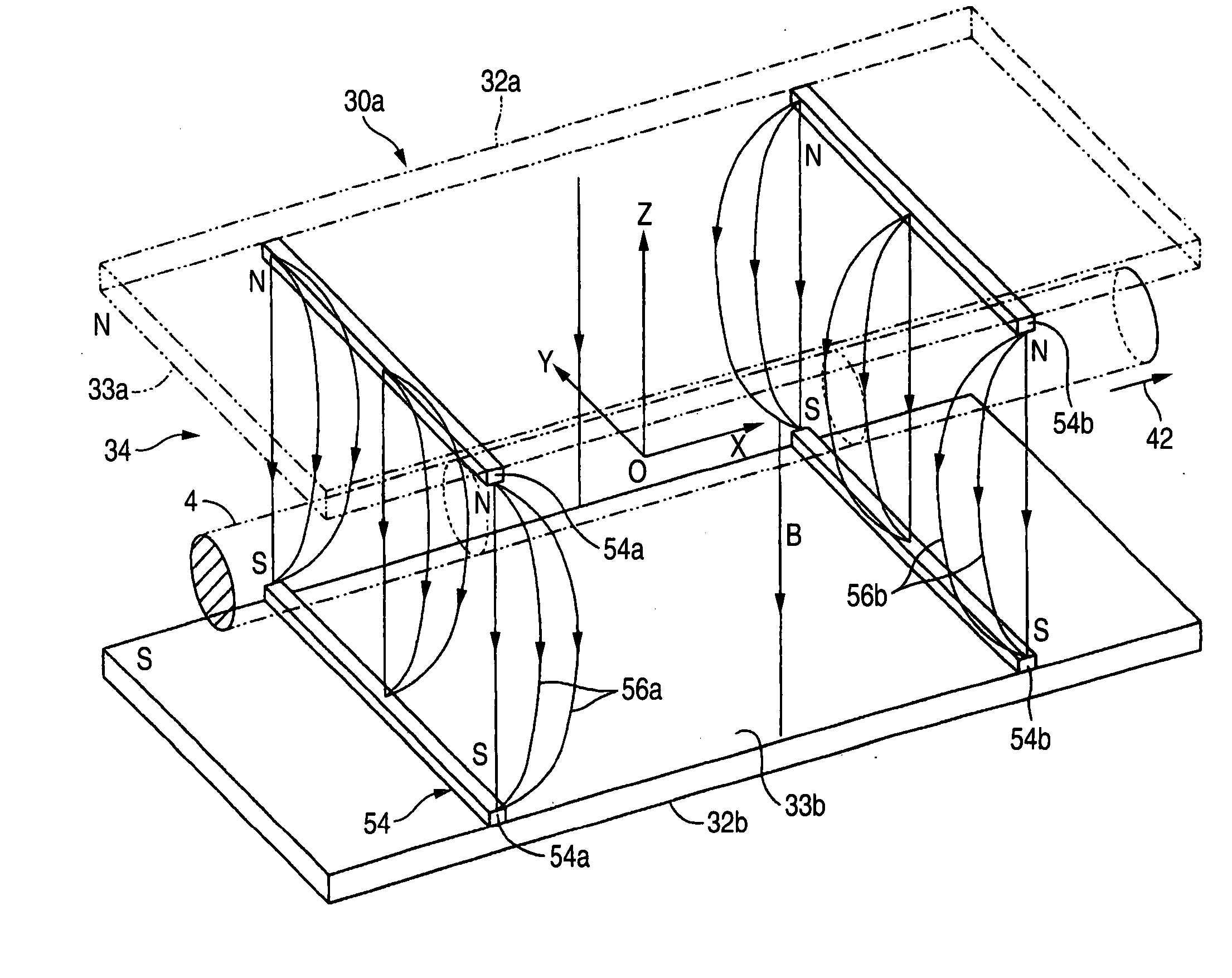
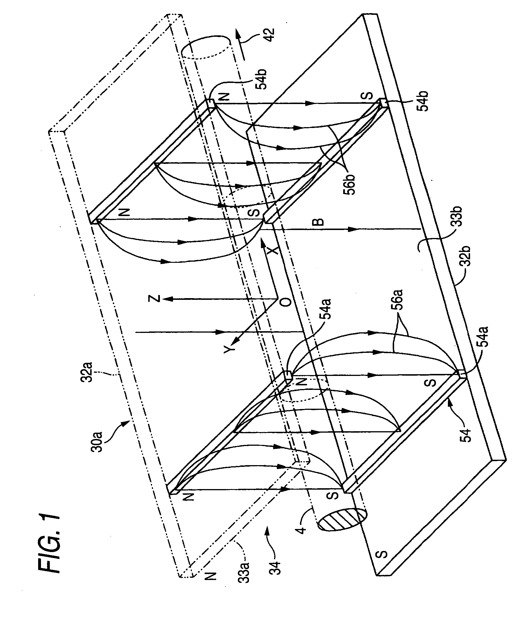
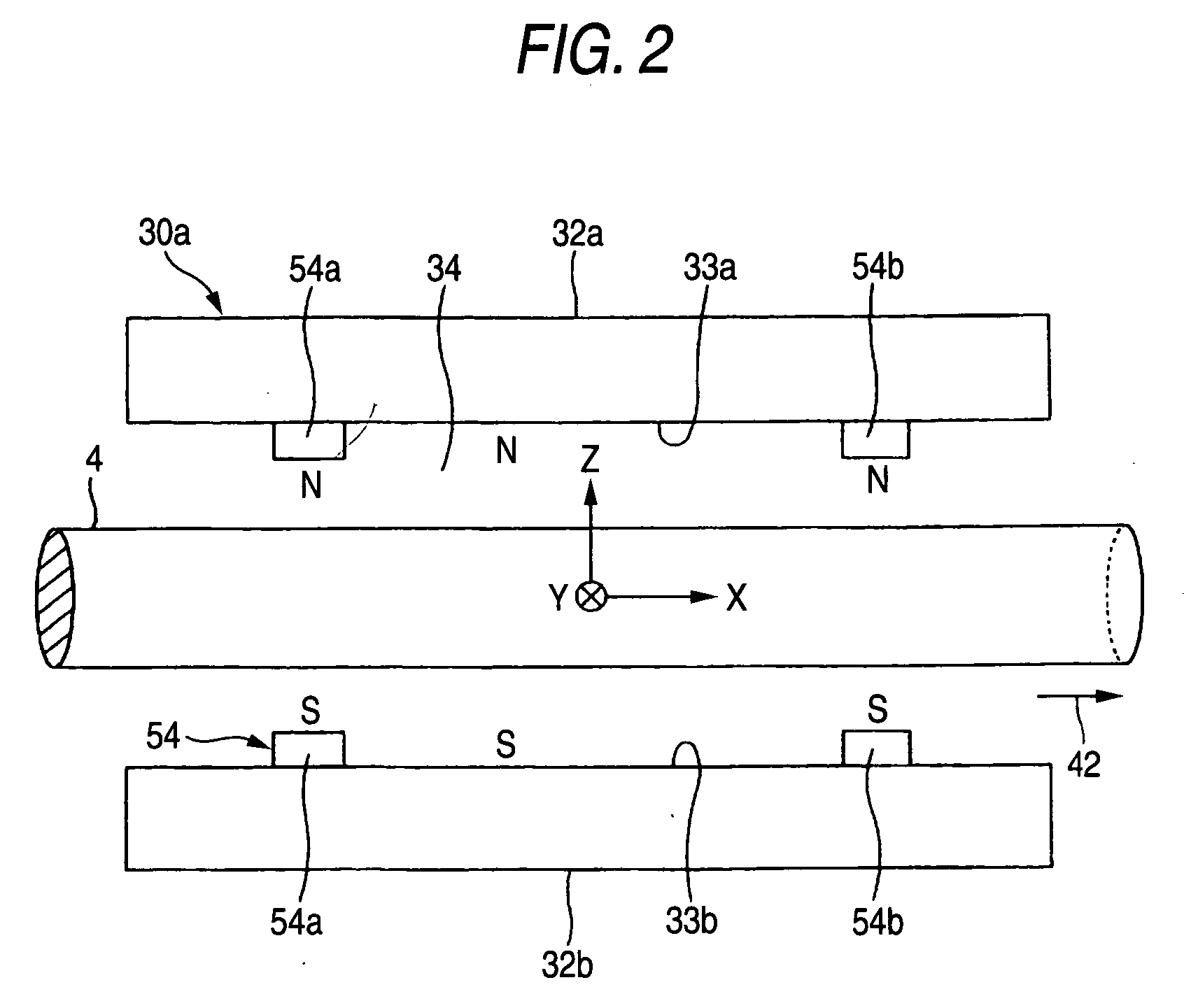
[0128]FIG. 1 is a schematic perspective view showing the deflecting electromagnet of the invention, and FIG. 2 is a schematic side view in which the deflecting electromagnet of FIG. 51 is seen from the lateral side of an ion beam passing direction, and illustration of magnetic force lines is omitted. The components which are identical or corresponding to those of the related-art example shown in FIGS. 58 to 60 are denoted by the same reference numerals. Hereinafter, description is made with placing emphasis on differences between the embodiment and the related-art example.

[0129] The deflecting electromagnet 30a comprises a permanent-magnet group 54 for, in an inter-pole space 34 between the first magnetic pole 32a and the second magnetic pole 32b, forming a mirror magnetic field in which the intensity is relatively low in the vicinity of the middle of the inter-pole space 34 in the ion beam passing direction, and the intensities in locations which are respectively nearer to the inle...

second embodiment

[0160] In FIG. 13, examples of the magnitude |E×B| of the E×B drift in the case where the deflecting electromagnet 30b of the second embodiment is cut along the YZ-plane are indicated by the areas of hatched parallelograms. Also an example of the magnetic force lines 66a, 66b produced by the paired permanent magnets 64a, 64b are shown in the figure. Since the permanent magnets 64a, 64b form a mirror magnetic field, also the composite magnetic field B of the magnetic field produced by the magnetic poles 32a, 32b and that produced by the paired permanent magnets 64a, 64b is formed as a mirror magnetic field.

[0161] For comparison, examples of the magnitude of the E×B drift in the YZ-plane of the deflecting electromagnet 30a of the first embodiment are shown in FIG. 12. Also an example of magnetic force lines 68 produced by the magnetic poles 32a, 32b is shown in the figure. In the case of the deflecting electromagnet 30a, the permanent-magnet group (specifically, the permanent magnets ...

third embodiment

[0178]FIG. 21 is a schematic longitudinal section view showing the deflecting electromagnet of the invention. The components which are identical or corresponding to those of the related-art example shown in FIGS. 58 to 60 are denoted by the same reference numerals. Hereinafter, description is made with placing emphasis on differences between the embodiment and the related-art example.

[0179] The deflecting electromagnet 30a comprises a pair of potential adjusting electrodes 152 which are placed so as to sandwich a path of the ion beam 4 in the same directions as the first and second magnetic poles 32a, 32b, in the inter-pole space 34 formed between the magnetic poles 32a, 32b. Specifically, the pair of plate-like potential adjusting electrodes 152 are placed respectively in the vicinities of the surfaces 33a, 33b of the magnetic poles 32a, 32b, while being electrically insulated from the magnetic poles 32a, 32b.

[0180] As shown in FIG. 21, etc., coordinate axes X, Y, Z which are orth...


PUM


Abstract

A deflecting electromagnet has first and second magnetic poles that are opposed to each other via an inter-pole space through which an ion beam passes. The deflecting electromagnet further has: a pair of potential adjusting electrodes which are placed to sandwich a path of the ion beam in the same directions as the magnetic poles in the inter-pole space; and a DC potential adjusting power source which applies a positive voltage to the potential adjusting electrodes. The deflecting electromagnet further has a permanent-magnet group for, in the inter-pole space, forming a mirror magnetic field in which intensity is low in the vicinity of the middle in an ion beam passing direction, and intensities in locations which are respectively nearer to an inlet and an outlet are higher than the intensity in the vicinity of the middle.

Description

TECHNICAL FIELD [0001] The present disclosure relates to a deflecting electromagnet which is to be used in an apparatus such as an ion beam irradiating apparatus for irradiating a target with an ion beam to perform ion implantation or the like, and which bends the ion beam by means of a magnetic field, and also to an ion beam irradiating apparatus which is provided with such a deflecting electromagnet. In the case where ion implantation is performed, the ion beam irradiating apparatus is called also as an ion implanting apparatus. RELATED ART [0002]FIG. 51 shows an example of such an ion beam irradiating apparatus. The ion beam irradiating apparatus has a configuration which irradiates a target 16 with an ion beam 4 emitted from an ion source 2. For example, the target 16 is a semiconductor substrate. [0003] Specifically, as disclosed also in Patent Reference 1 (Japanese Patent Unexamined Publication No. 2001-143651 (Paragraphs 0004 to 0005, FIG. 4)), the ion beam irradiating appara...

Claims


Application Information

Patent Timeline
Patent Type & Authority Applications(United States)
IPC IPC(8): H01J1/50
CPCH01J37/1475H01J2237/152H01J2237/31701
Inventor FUJITA, HIDEKI
Owner NISSIN ION EQUIP CO LTD
Why Eureka
Try Eureka