Film formation apparatus and methods including temperature and emissivity/pattern compensation

a film formation apparatus and temperature-emitting technology, applied in the direction of liquid surface applicators, coatings, chemical vapor deposition coatings, etc., can solve the problems affecting both accuracy and accuracy, and achieve the effect of enhancing the absorption of overlapped surfaces and enhancing light scattering or light absorption effects

Inactive Publication Date: 2007-04-05
APPLIED MATERIALS INC
View PDF27 Cites 432 Cited by
  • Summary
  • Abstract
  • Description
  • Claims
  • Application Information

AI Technical Summary

Benefits of technology

[0010] In another embodiment, an outer edge portion of the substrate support overlaps with the inner peripheral edge of the peripheral member, thereby blocking light that emanates from below the substrate. In one embodiment, the substrate support may be rotatably mounted within the system, and the inner peripheral edge of the peripheral member does not touch the outer edge of the substrate support. In another embodiment, either of the ov...

Problems solved by technology

First, high temperature atmospheric epitaxial applications, typically using trichlorosilane as the silicon precursor gas, are mass-transport limited processes.
A second factor that affects equipment performance for these new processes is the need t...

Method used


Image

  • Film formation apparatus and methods including temperature and emissivity/pattern compensation
  • Film formation apparatus and methods including temperature and emissivity/pattern compensation
  • Film formation apparatus and methods including temperature and emissivity/pattern compensation

Examples


Embodiment Construction

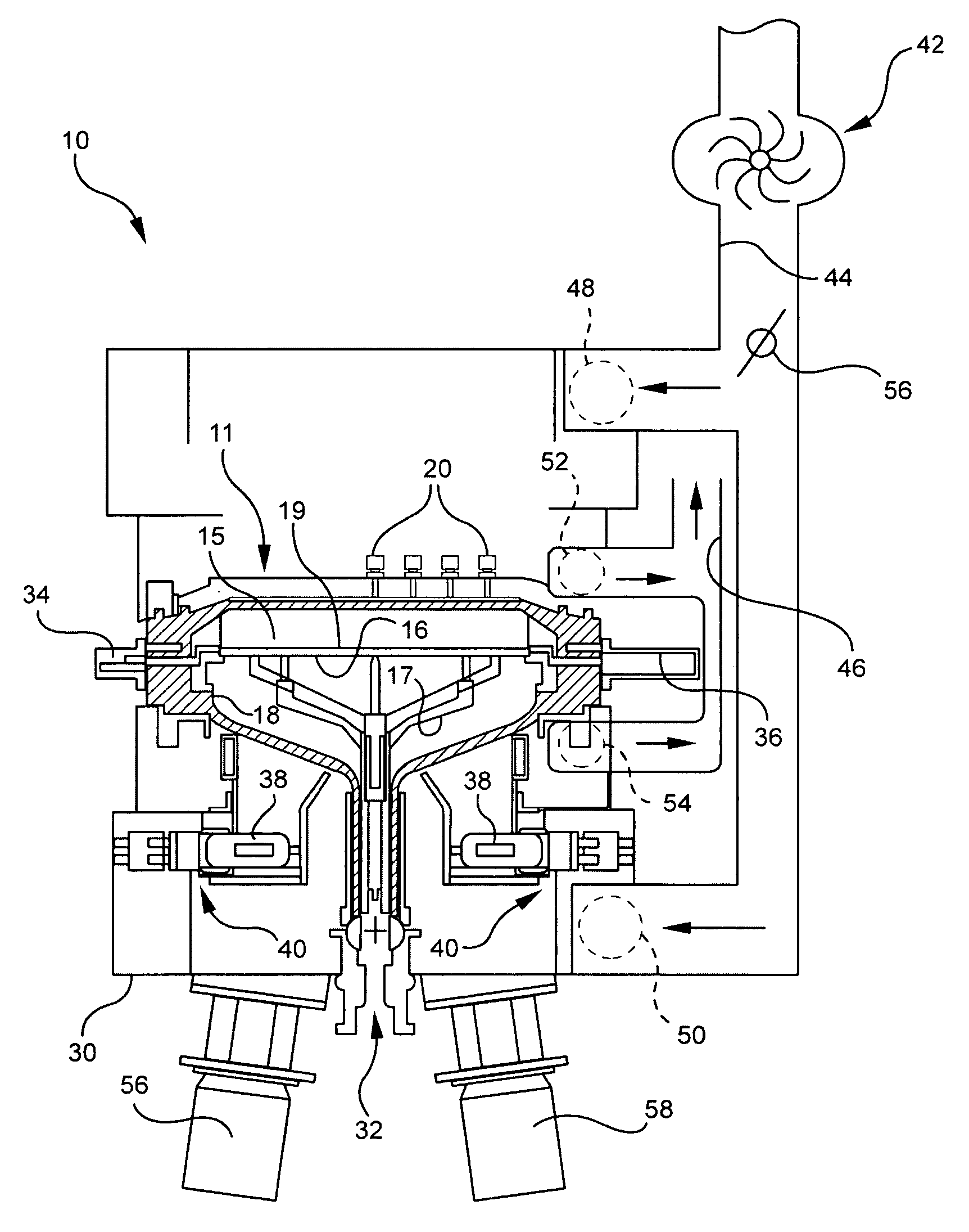
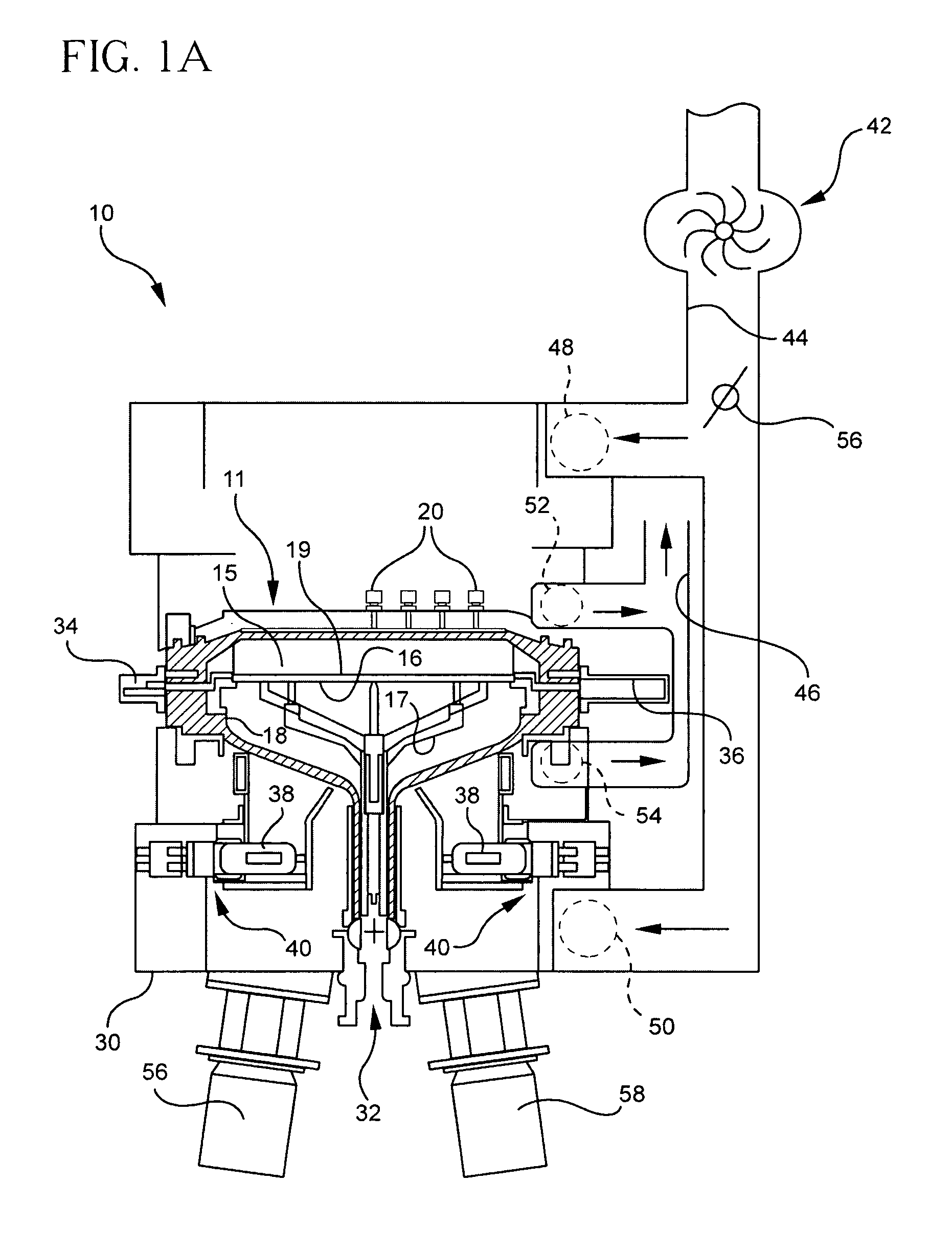
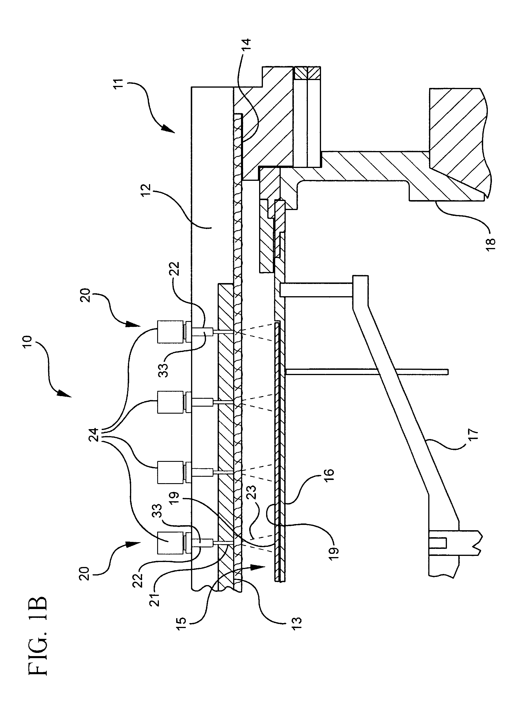
[0028] Several exemplary embodiments of the present invention are disclosed herein. It should be understood, however, that the disclosed embodiments are merely exemplary of the invention, which may be embodied in many forms. Therefore, the details disclosed herein are not to be interpreted as limiting, but merely as the basis for claims and as a basis for teaching one skilled in the art how to make and use the invention. A schematic view of a film formation system 10 is shown in FIGS. 1A and 1B. The system 10, which may be, for example, a CVD epitaxial system, a poly silicon or silicon nitride deposition system, or any other film deposition system for hot CVD processes, i.e., CVD processes that are around 400° C. or greater. The system 10 includes a processing chamber 15 bounded by sidewalls 18. Examples of such systems are disclosed in commonly assigned U.S. Pat. Nos. 5,108,792; 5,258,824; and 6,083,323, each of which is incorporated herein by reference. The sidewalls 18 may be mad...


PUM

PropertyMeasurementUnit
Poweraaaaaaaaaa
Temperatureaaaaaaaaaa
Thermal conductivityaaaaaaaaaa

Abstract

A film formation system 10 has a processing chamber 15 bounded by sidewalls 18 and a top cover 11. In one embodiment, the top cover 11 has a reflective surface 13 for reflecting radiant energy back onto a substrate 19, pyrometers 405 for measuring the temperature of the substrate 19 across a number of zones, and at least one emissometer 410 for measuring the actual emissivity of the substrate 19. In another embodiment, a radiant heating system 313 is disposed under the substrate support 16. The temperature of the substrate 19 is obtained from pyrometric data from the pyrometers 405, and the emissometer 410.

Description

TECHNICAL FIELD [0001] Embodiments of the invention generally relate to reaction chambers and film formation apparatus and methods. [0002] Over the last several years, there has been a significant increase in the number of applications requiring low temperature deposition of single crystal silicon films. Examples of those applications include but are not limited to blanket silicon germanium films, elevated and / or recessed source drain selective deposition, films with either tensile or compressive strains, etc. Depending on the particular application, these processes can all differ greatly in the pressure, temperature and chemicals that are used to grow the films. However, one requirement these processes have in common is that they all require very careful, accurate and uniform control of the temperature of the wafer. [0003] Single wafer silicon deposition CVD chambers (for both 200 mm and 300 mm applications) have been available for many years now. This equipment, however, was desig...

Claims


Application Information

Patent Timeline
IPC IPC(8): C23C16/00
CPCC23C16/481C23C16/52C23C16/00
Inventor CHACIN, JUANHUNTER, AARONMETZNER, CRAIGANDERSON, ROGER N.
Owner APPLIED MATERIALS INC
Why Eureka
Try Eureka