Venous reservoir

a technology of veins and reservoirs, applied in the field of veins, to achieve the effect of enhancing advantages and uniqueness, and a larger screen area

Inactive Publication Date: 2007-04-05
TAMARI YEHUDA
View PDF23 Cites 27 Cited by
  • Summary
  • Abstract
  • Description
  • Claims
  • Application Information

AI Technical Summary

Benefits of technology

[0022] The present invention incorporates improved designs for venous reservoirs that provide the benefits of prior art devices (limiting pump suction using the safer, pliable blood reservoir) while avoiding their disadvantages (air entrapment, inability to utilize VAVD, required vigilance for air removal). Further, its advantages and uniqueness are also enhanced by providing the user with means to adjust the degree of suction applied for venous augmentation and assuring that a greater area of the screen is effective in liquid transport.
[0023] Briefly, the present invention in its simplest form consists of a blood reservoir having at least one pliable wall, a blood inlet, a blood outlet, and a gas purge port. In one preferred embodiment, a first structure having tubular cross section and semirigid wall is placed above said inlet thereby providing a first path for undesirable bubbles entering the reservoir to move to the top where they are eliminated via said gas purge port. The first structure preferably has an effective cross section that is larger than the ID of said inlet tube thereby slowing any blood flow and allowing more favorable conditions (longer time, lower drag) for gas bubbles to float upward. The wall of the first structure is sufficiently rigid to prevent collapse of said pliable wall from blocking said first path. In another preferred embodiment, the pliable wall of the venous reservoir is sealed externally, forming a pressure chamber external to the venous reservoir. Controlled suction applied to said external chamber is transmitted across said pliable wall thereby controlling the negative pressure of the blood at which said pliable wall moves.
[0024] Another preferred embodiment has all the tubes at the top of the SSR. These tubes pass through, sealed within, and physically supported by a rigid disposable supporting plate providing three major advantages. First, the bag is supported by hanging the supporting plate in a supporting fixture, much like the hard shell reservoir. This allows the user to “drop in” the SSR and just as easily remove the SSR from its holder. Second, the supporting plate provides simple sealing means along a single plane, an extremely important feature for simple and secure sealing of the SSR within housing for VAVD applications. Third, by having all the tubes for the bag entering from its top, the bottom of the bag is unhindered and can be placed lower to the floor allowing greater gravity drainage. In addition, because the bag hangs from the top, the weight of the SSR / blood contributes to the seal of the supporting plate against the housing. Designed properly, this gravitational force can eliminate or greatly simplify any clamping required by other designs.

Problems solved by technology

In addition, because the bag hangs from the top, the weight of the SSR / blood contributes to the seal of the supporting plate against the housing.

Method used


Image

  • Venous reservoir
  • Venous reservoir
  • Venous reservoir

Examples


Embodiment Construction

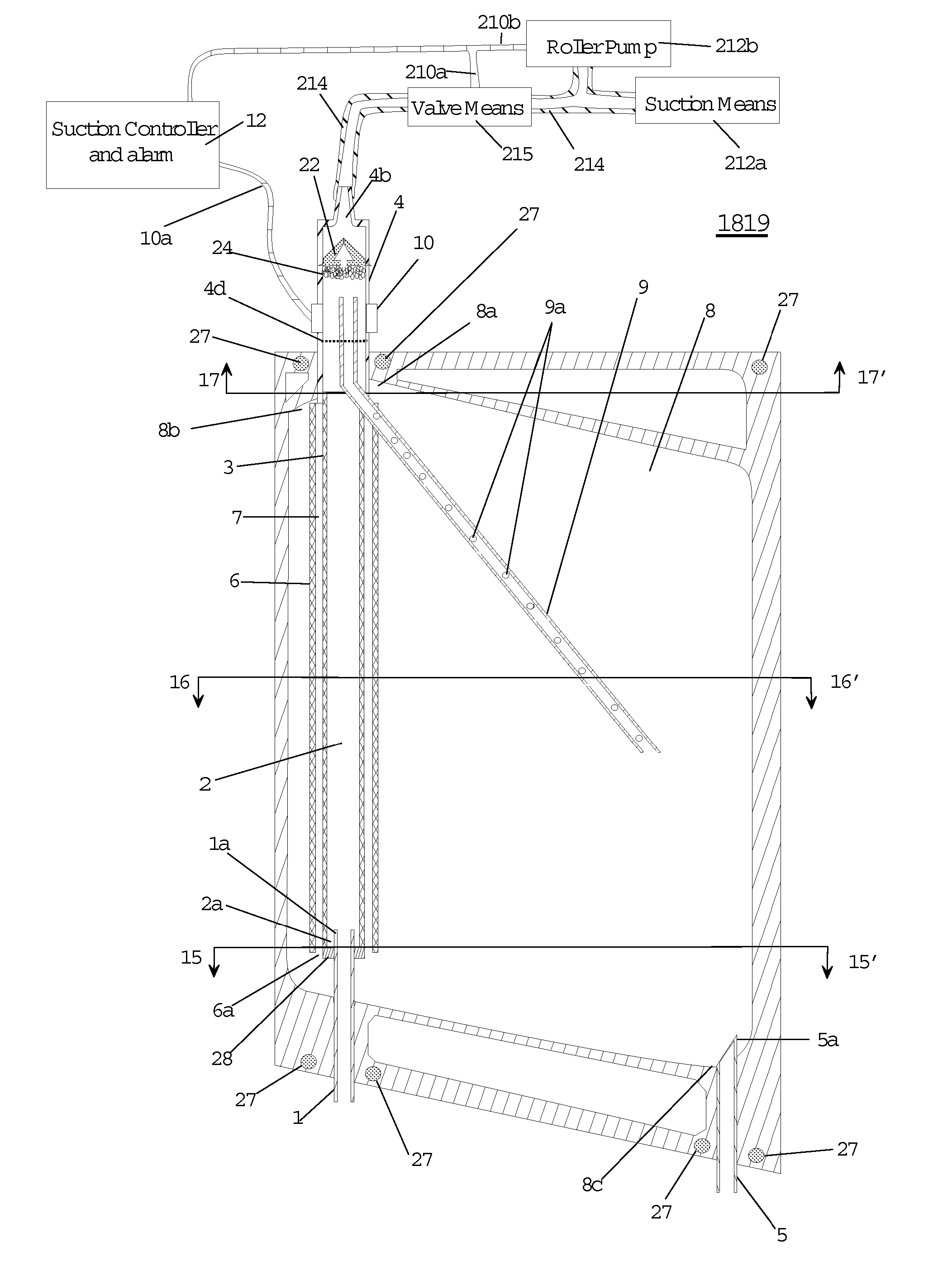
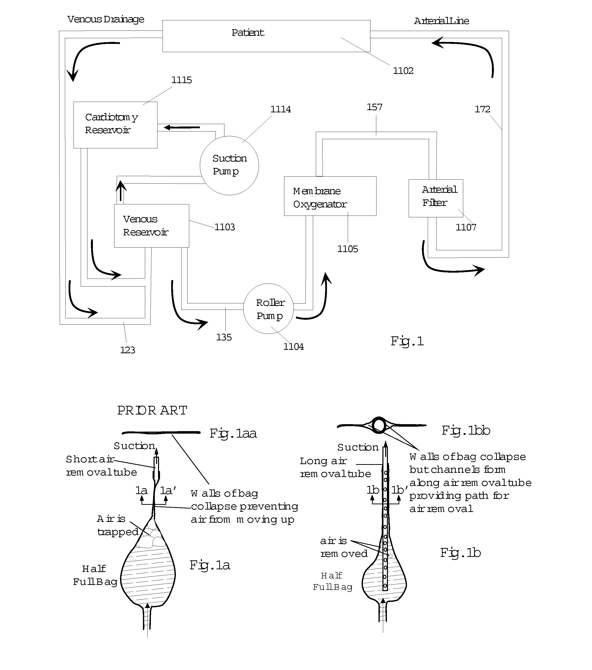
[0099] Reference should now be made to the drawings wherein the same reference numerals are used throughout to designate the same or similar parts. It should be noted that the use of cardiopulmonary bypass, as shown in FIG. 1, is for descriptive purposes, and should not be taken as a limitation to the use of the devices described hereinafter. It should also be noted that the term soft shell reservoir, venous bag and bag are used interchangeably.

[0100]FIG. 1 is a schematic representation of a system according to the present invention and showing the relative location of the venous reservoir in a typical cardiopulmonary bypass circuit. As shown, tubing 123 is inserted at one end by means of a cannula (not shown) in the vena cavae for obtaining venous blood from the heart (not shown) of patient 1102. Tubing 123 is coupled, as an example, to venous reservoir 1103. The blood is drawn from venous reservoir 1103 via tube 135 by roller pump 1104 and pumped through a membrane oxygenator 110...


PUM


Abstract

Venous reservoirs are interposed between the patient and the arterial pump and serve to remove air bubbles and provide compliance that accommodates variations in the volume of blood circulating in the extracorporeal circuit during cardiopulmonary bypass (CPB). The invention is a reservoir that incorporates automated means to remove air bubbles from the venous line prior to the blood entering the arterial blood pump. In another form, the reservoir includes means that handles foam prior to the blood entering the blood pump. In yet another form, the invention is means that improve air removal in a soft shell venous reservoir. These features are applicable to CPB circuits using gravity drainage or vacuum assisted venous drainage.

Description

CROSS-REFERENCE TO RELATED APPLICATIONS [0001] This is a divisional application of allowed U.S. Application Ser. No. 10 / 915,000 filed Aug. 9, 2004, now allowed U.S. patent to be issued Nov. 7, 2006, U.S. application Ser. No. 09 / 795,782 filed Feb. 28, 2001, now allowed U.S. Pat. No. 6,773,426 issued Aug. 10, 2004, application PCT / US99 / 19477 filed Aug. 30, 1999 (now published as WO012155A1: “An Improved Soft Shell Venous Reservoir”), and U.S. application Ser. No. 09 / 141,960 filed Aug. 28, 1998 now U.S. Pat. No. 6,337,049, the disclosures of these applications and patents being incorporated herein by reference thereto.GOVERNMENT INTERESTS [0002] This invention was in part made with government support under SBIR Grant #R44HL-55034 awarded by the National Institute Health, National Heart, Lung, and Blood Institute. As such the government may have certain rights in the invention.BACKGROUND OF THE INVENTION [0003] 1. Field of the Invention [0004] The invention is a blood reservoir with at ...

Claims


Application Information

Patent Timeline
Patent Type & Authority Applications(United States)
IPC IPC(8): A61M37/00A61M1/36
CPCA61M1/3621A61M1/3627Y10S128/03A61M1/3667
Inventor TAMARI, YEHUDA
Owner TAMARI YEHUDA
Why Eureka
Try Eureka