Diamond-bonded bodies and compacts with improved thermal stability and mechanical strength

Inactive Publication Date: 2007-04-12
SMITH INT INC
View PDF6 Cites 281 Cited by
  • Summary
  • Abstract
  • Description
  • Claims
  • Application Information

AI Technical Summary

Benefits of technology

[0015] The infiltrant or replacement material is added or combined with the diamond-bonded body and the diamond-bonded body and the infiltrant material are subjected to a high pressure/high temperature process to melt the infiltrant material. The infiltrant material fills at least a portion or population of the voids,

Problems solved by technology

A problem known to exist with such conventional PCD materials is thermal degradation due to differential thermal expansion characteristics between the interstitial solvent catalyst material and the intercrystalline bonded diamond.
Such differential thermal expansion is known to occur at temperatures of about 400° C., causing ruptures to occur in the diamond-to-diamond bonding, and resulting in the formation of cracks and chips in the PCD structure.
Another problem known to exist with conventional PCD materials is also related to the presence of the solvent catalyst material in the interstitial regions and the adherence of the solvent catalyst to the diamond crystals to cause another form of thermal degradation.
Specifically, the solvent catalyst material is known to cause an undesired catalyzed phase transformation in diamond (converting it to carbon monoxide, carbon dioxide, or graphite) with increasing temperature, thereby limiting practical use of the PCD material to about 750° C.
However, the resulting thermally stable diamond-bonded body typically does not include a metallic substrate attached thereto, by solvent catalyst infiltration from such substrate due to the solvent catalyst removal process, as all of the solvent catalyst material has been removed therefrom.
This difference in thermal expansion between the now thermally stable diamond-bonded body and the substrate, combined with the poor wetability of the diamond-bonded

Method used


Image

  • Diamond-bonded bodies and compacts with improved thermal stability and mechanical strength
  • Diamond-bonded bodies and compacts with improved thermal stability and mechanical strength
  • Diamond-bonded bodies and compacts with improved thermal stability and mechanical strength

Examples


Embodiment Construction

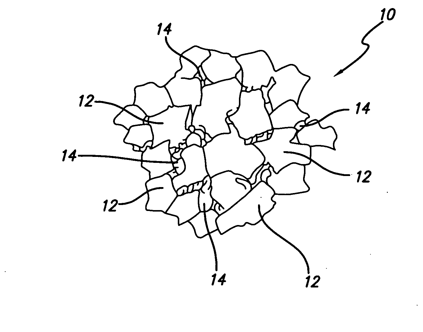
[0029] Thermally stable diamond-bonded materials and compacts of this invention are specifically engineered having a diamond-bonded body comprising a thermally stable diamond-bonded region, thereby providing improved thermal stability when compared to conventional PCD materials. The thermally stable diamond-bonded region comprises a polycrystalline matrix first phase and a second phase disposed interstitially between the bonded diamond crystals forming the matrix first phase. The second phase occupies all or a population of voids or pores in the microstructure that were formed by the removal of a solvent catalyst material. In an example embodiment, the second phase is formed from a material that is different from the metal solvent catalyst used to form conventional PCD.

[0030] As used herein, the term “PCD” is used to refer to polycrystalline diamond that has been formed, at high pressure / high temperature (HPHT) conditions, through the use of a metal solvent catalyst, such as those ...


PUM

PropertyMeasurementUnit
Timeaaaaaaaaaa
Depthaaaaaaaaaa
Temperatureaaaaaaaaaa

Abstract

Thermally stable diamond-bonded compacts include a diamond-bonded body having a thermally stable region extending a distance below a diamond-bonded body surface. The thermally stable region comprises a matrix first phase of bonded together diamond crystals, and a second phase interposed within the matrix phase. At least some population of the second phase comprises a reaction product formed between an infiltrant material and the diamond crystals at high pressure/high temperature conditions. The diamond bonded body further includes a polycrystalline diamond region that extends a depth from the thermally stable region and has a microstructure comprising a polycrystalline diamond matrix phase and a catalyst material disposed within interstitial regions of the matrix phase. The compact includes a substrate attached to the diamond-bonded body.

Description

FIELD OF THE INVENTION [0001] This invention generally relates to diamond-bonded materials and, more specifically, to polycrystalline diamond materials and compacts formed therefrom that are specially engineered to provide improved properties of thermal stability and mechanical strength when compared to conventional polycrystalline diamond materials. BACKGROUND OF THE INVENTION [0002] Polycrystalline diamond (PCD) materials and PCD elements formed therefrom are well known in the art. Conventional PCD is formed by combining diamond grains with a suitable solvent catalyst material to form a mixture. The mixture is subjected to processing conditions of extremely high pressure / high temperature, where the solvent catalyst material promotes desired intercrystalline diamond-to-diamond bonding between the grains, thereby forming a PCD structure. The resulting PCD structure produces enhanced properties of wear resistance and hardness, making PCD materials extremely useful in aggressive wear ...

Claims


Application Information

Patent Timeline
IPC IPC(8): E21B10/36
CPCC04B35/52C04B35/645C04B37/021C04B2235/3826C04B2235/427C04B2235/428E21B10/573C04B2235/616C04B2235/80C04B2237/363C04B2237/401C04B2237/61C04B2235/5436
Inventor MIDDLEMISS, STEWART N.
Owner SMITH INT INC
Why Eureka
Try Eureka